Card reader based on RF radio frequency communication

A technology of radio frequency communication and card reader, which is applied in the field of card readers based on RF radio frequency communication, can solve problems such as high cost, unsuitability for purposes, complex structure and functions of card readers, etc., and achieve reduced production costs, simple working principle, Ease of use

Inactive Publication Date: 2017-01-18
JIANGMEN HUILANG IND ROBOT CO LTD
5 Cites 0 Cited by

AI-Extracted Technical Summary

Problems solved by technology

However, the structure and function of the card reader for this signal frequency in the existing design are comp...

Method used

[0020] The present invention adopts a modular design, which simplifies the circuit structure of the card reader while meeting the safety requir...

Abstract

The invention discloses a card reader based on RF radio frequency communication. The card reader comprises a processor, a crystal oscillation circuit, a radio frequency transmit-receive circuit, a signal generation circuit, an antenna, a power supply module and an SAM card. The processor is respectively connected with the crystal oscillation circuit, the radio frequency transmit-receive circuit and the SAM card. The radio frequency transmit-receive circuit is respectively connected with the signal generation circuit, the antenna and the power supply module. The radio frequency transmit-receive circuit is used for modulating and demodulating radio frequency signals of which the frequency is 13.56MHz. The signal generation circuit outputs carrier signals of which the frequency is 13.56MHz to the radio frequency transmit-receive circuit. The SAM card can provide a security mechanism. The security requirement is met and the circuit structure of the card reader is simplified so that use is facilitated for users, and production cost is also greatly reduced. The card reader based on RF radio frequency communication is generally used for reading the data stored in an electronic tag of the specific signal frequency.

Application Domain

Technology Topic

Image

  • Card reader based on RF radio frequency communication
  • Card reader based on RF radio frequency communication

Examples

  • Experimental program(1)

Example Embodiment

[0017] In the following, the concept, specific structure and technical effects of the present invention will be clearly and completely described in conjunction with the embodiments and the drawings to fully understand the purpose, features and effects of the present invention. Obviously, the described embodiments are only a part of the embodiments of the present invention, rather than all of them. Based on the embodiments of the present invention, other embodiments obtained by those skilled in the art without creative work belong to The scope of protection of the present invention. The various technical features in the invention can be combined interactively on the premise of not conflicting with each other.
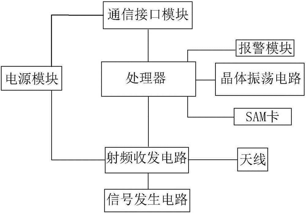
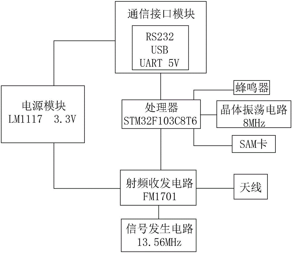
[0018] Reference figure 1 The invention of the present invention is a card reader based on RF radio frequency communication, including a processor, a crystal oscillator circuit, a radio frequency transceiver circuit, a signal generating circuit, an antenna, a power module and a SAM card. The processor is connected to the crystal oscillator circuit, The radio frequency transceiver circuit is connected to the SAM card, and the radio frequency transceiver circuit is respectively connected to the signal generating circuit, the antenna and the power module. The feature is that the radio frequency transceiver circuit is used to modulate and demodulate a radio frequency signal with a frequency of 13.56 MHz. The generating circuit outputs a carrier signal with a frequency of 13.56MHz to the radio frequency transceiver circuit. The SAM card can provide a security mechanism for decryption and encryption operations during radio frequency signal reception and transmission, or to perform other operations on the received data. Identification of legality.
[0019] The working principle of the present invention is as follows: when the card reader performs the card reading operation, the antenna converts nearby magnetic field energy into electrical signals of various frequencies, and then the radio frequency transceiver circuit demodulates, amplifies and processes the radio frequency signal with a frequency of 13.56MHz. Digital signal, and then transmit the signal to the processor, then the processor uses the SAM card to decrypt the collected signal, or to identify the signal and determine its legitimacy, the SAM card then feeds back the processed result to the processor , The processor performs related calculations according to the feedback results and the set program; when the card reader performs the card writing operation, the processor first configures the relevant parameters of the radio frequency transceiver circuit, such as the power of the transmitted signal, and then the processor will pass through the SAM card The encrypted data is stored in the relevant registers of the radio frequency transceiver circuit. The radio frequency transceiver circuit modulates the baseband signal into a 13.56MHz modulation signal by using the carrier signal transmitted by the signal generating circuit, and finally converts the electrical signal of this frequency into a magnetic field signal through the antenna And send it out.
[0020] The invention adopts a modular design, which simplifies the circuit structure of the card reader while meeting safety requirements, is convenient for users to use, greatly reduces production costs, and is suitable for a single low-end user group with a single required purpose.
[0021] Reference figure 2 Shown is a schematic circuit diagram of an embodiment of the present invention.
[0022] In this embodiment, the model STM32F103C8T6 is used as the processor, and the crystal oscillator circuit provides an 8MHz clock signal to the processor. Of course, the present invention is not limited to this model of processor. Any control chip that meets the requirements in terms of operating speed and hardware resources Both can be used as the processor of the present invention. In addition, the operating speed of the processor depends on the frequency of the clock signal provided by the crystal oscillator circuit. Therefore, in practical applications, those skilled in the art can adjust the clock signal output by the crystal oscillator circuit. Frequency to meet design requirements.
[0023] Further, the radio frequency transceiver circuit in this embodiment is composed of a universal card reader chip with model FM1701 and its peripheral circuits. The signal generating circuit is a crystal oscillator, and the carrier signal frequency provided to the radio frequency transceiver circuit is 13.56 MHz. The model FM1701 chip is configured to support Type A non-contact communication protocol at 13.56MHz frequency, so it needs to be used in conjunction with a signal generating circuit that can generate a corresponding frequency signal, and this model chip is a highly integrated analog circuit , Less peripheral circuits are required, so the circuit structure of the card reader is simplified to a large extent, and the cost is reduced.
[0024] In addition to the FM1701 in this embodiment, the card reader chip can also be any highly integrated chip configured to perform similar functions; in addition, the signal generating circuit in the present invention is not limited to the crystal in this embodiment. Oscillators and other signal generators that can perform similar functions fall within the protection scope created by the present invention.
[0025] Further, the power module in this embodiment is composed of a voltage stabilizing chip with a model number of LM1117 and its peripheral circuits. The power module provides external voltages of 1.5V and/or 1.8V and/or 2.5V and/or 3.3V and / Or 5V. A person skilled in the art can determine the voltage that the power supply module needs to provide according to the power supply voltage required by each module in the circuit, and then connect different voltage interfaces of the power supply module to the corresponding circuit module. Of course, the power supply module with the LM1117 as the core is only one embodiment of the power supply module in the present invention, and the power supply module may also be various power supply circuits on the premise of outputting the actual required voltage.
[0026] Further, this embodiment also includes a communication interface module, the communication interface module is respectively connected to the power supply module and the processor, the processor can perform two-way data transmission with external devices through the communication interface module, the communication interface module includes an RS232 interface and/ Or a USB interface and/or a UART interface, which is compatible with various levels. The communication interface module can also be used as a medium for external equipment to provide input voltage to the power module. The power module then converts the input voltage into a specified output voltage to provide voltage for other circuit modules. The integration of various common communication interfaces is for The various devices of the above-mentioned interfaces communicate with each other and transfer required data. In addition, the required communication interfaces can be expanded according to actual conditions.
[0027] Further, this embodiment also includes an alarm module, the alarm module is connected to the processor, and the alarm module includes a buzzer that serves as an alarm reminder. Of course, the device that can complete the function of the alarm module is not limited to this embodiment. The said buzzer, any device that can complete the similar prompt function belongs to the protection scope of the present invention.
[0028] The preferred embodiments of the present invention are described in detail above, but the invention is not limited to the described embodiments. Those skilled in the art can make various equivalent modifications or substitutions without departing from the present invention. These Equivalent modifications or replacements are all included in the scope defined by the claims of this application.

PUM

no PUM

Description & Claims & Application Information

We can also present the details of the Description, Claims and Application information to help users get a comprehensive understanding of the technical details of the patent, such as background art, summary of invention, brief description of drawings, description of embodiments, and other original content. On the other hand, users can also determine the specific scope of protection of the technology through the list of claims; as well as understand the changes in the life cycle of the technology with the presentation of the patent timeline. Login to view more.

Similar technology patents

Anti-failure pneumatic window opener

ActiveCN109914958ASimple working principleThe structure is easy to disassemblePower-operated mechanismWing openersPistonAir spring
Owner:郑州洪华建筑科技有限公司

Classification and recommendation of technical efficacy words

  • Simple working principle
  • Easy to use

Safety rod driving system of liquid heavy metal cooling reactor

Owner:HEFEI INSTITUTES OF PHYSICAL SCIENCE - CHINESE ACAD OF SCI

Laser assisted total joint arthroplasty

InactiveUS20090234360A1Easy to useNon-surgical orthopedic devicesSurgical sawsLaser assistedLaser guidance
Owner:ALEXANDER VLADIMIR

System, method, and apparatus for settlement for participation in an electric power grid

ActiveUS8583520B1Communication securityEasy to useLevel controlCoin-freed apparatusNetwork managementGrid operator
Owner:CAUSAM ENERGY INC
Why Eureka
Try Eureka