Alternating hybrid excitation component and application thereof in motor and transformer

A composite excitation and component technology, applied in the field of electric motors, can solve the problems of reducing the magnetic field contribution of permanent magnets, reducing the combined efficiency of excitation and permanent magnets, and unable to obtain the alternating magnetic field of magnetic field strength, so as to improve stability, save permanent magnet materials, The effect of torque stability improvement

Inactive Publication Date: 2017-01-18
戴珊珊
View PDF13 Cites 2 Cited by
  • Summary
  • Abstract
  • Description
  • Claims
  • Application Information

AI Technical Summary

Problems solved by technology

When an alternating excitation current is input into the excitation coil, if a permanent magnet is embedded in the single iron core, the compound excitation magnetic field can only be generated under the excitation condition of the excitation current in a certain direction, and the magnetic field cannot be obtained at the magnetic pole surface of the single iron core. An alternating magnetic field of equal strength
If two permanent magnets with opposite magnetic poles are embedded in the single core, when an alternating excitation current is input into the excitation coil, the magnetic circuit interference between the two permanent magnets and the excitation field will partially reduce the excitation and permanent magnet recombination efficiency , thus reducing the contribution of the permanent magnet field to the composite excitation potential

Method used


Image

  • Alternating hybrid excitation component and application thereof in motor and transformer
  • Alternating hybrid excitation component and application thereof in motor and transformer
  • Alternating hybrid excitation component and application thereof in motor and transformer

Examples


Embodiment 1

[0054] This embodiment is an alternating compound excitation assembly using a double-layer C-shaped iron core.

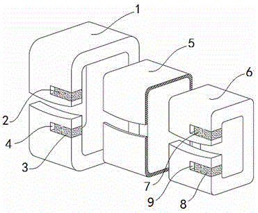
[0055] attached figure 1 A schematic diagram of the expanded structure of the double-layer C-shaped iron core alternating compound excitation assembly of this embodiment is given.

[0056] In this embodiment, the C-shaped iron core is divided into inner and outer layers, the outer layer iron core 1 and the inner layer iron core 6, and a magnetic isolation layer 5 is arranged between the two layers of iron cores; Each has two gaps, which are respectively embedded in the permanent magnet 2 and the permanent magnet 3. The magnetic polarity directions of the permanent magnet 2 and the permanent magnet 3 are the same, that is, the upper part is the N pole, and the lower part is the S pole. There is a gap 4 between the side and the outer iron core 1, and two gaps are respectively opened on the inner iron core 6, and the permanent magnet 7 and the permanent magnet 8 are e...

Embodiment 2

[0064] This embodiment is an application of an alternating compound excitation assembly in a switched reluctance rotating electrical machine. The motor structure of this embodiment is as attached Figure 8 shown.

[0065] Ten C-shaped alternating compound excitation components are ring-shaped, balanced and symmetrically arranged on the stator seat, and each alternating compound excitation component is magnetically isolated from each other, a circular bracket 21, a rotating shaft 22, and sixteen permanent magnets 23 together form the rotor.

[0066] The structure of ten C-shaped alternating compound excitation components is as attached figure 1 to attach Figure 7 As shown, the iron core of the C-shaped alternating composite excitation assembly is double-layer C-shaped, and a C-shaped magnetic isolation layer is arranged between the two layers of C-shaped iron cores. Gap, two permanent magnets are inlaid in the two rectangular notches respectively, the magnetic polarities o...

Embodiment 3

[0076] This embodiment is another application form of the alternating compound excitation assembly in the switched reluctance rotating electrical machine. The motor structure of this embodiment is as attached Figure 9 shown.

[0077] The six C-shaped alternating compound excitation components are ring-shaped, balanced and symmetrically arranged on the stator seat, and the alternating compound excitation components are magnetically isolated from each other. The circular bracket 31, the rotating shaft 32, the four permanent magnets 33 and the four The four magnetic conductors 39 together constitute the rotor.

[0078] The structure of the six C-shaped alternating compound excitation components is as attached figure 1 to attach Figure 7 As shown, its working principle is referred to Embodiment 1.

[0079] Four permanent magnets 33 and four magnetizers 39 are alternately embedded in the circular support 31, there is a gap between the adjacent permanent magnets and the magnet...


PUM


Abstract

The invention relates to an alternating hybrid excitation component and an application of the alternating hybrid excitation component in a rotary motor, a linear motor and a transformer. The alternating hybrid excitation component comprises even-number layers of iron cores and a plurality of magnetic isolation layers, wherein the magnetic isolation layers are arranged between the layers of the iron cores, the even-number layers of the iron cores and the magnetic isolation layers form the shape of a closed loop or an open loop, one or two gaps are formed in each layer of the iron core, a permanent magnet is inlaid at the gap in each layer of the iron core, two magnetic pole faces of the permanent magnet are clung to two opposite sides of the gap of the iron core, and a clearance is left between one lateral surface of the permanent magnet and the lateral side of the gap of the iron core; furthermore, the magnetic polarity directions of the permanent magnets inlaid at the gaps in every two adjacent layers of the iron cores are different, and exciting coils in a same set surround the periphery of each layer of the iron core. The alternating hybrid excitation component superposes permanent magnet magnetic potentials and excitation magnetic potentials to form an alternating hybrid excitation magnetic field, so that the electromagnetic energy efficiency can be improved. The invention further provides examples of the alternating hybrid excitation component applied to the rotary motor, the linear motor and the transformer.

Description

technical field [0001] The invention relates to motor technology, in particular to a compound excitation component capable of generating alternating compound magnetic fields, an alternating compound excitation rotating motor, a linear motor and an alternating compound excitation gain transformer device constructed by using the component. Background technique [0002] In the traditional switched reluctance motor stator, the permanent magnetic potential of the permanent magnet and the excitation magnetic potential of the exciter are combined to act on the motor rotor, which creates a new technical approach for improving the efficiency of the motor. Chinese patent CN201010102546.x (Nanjing University of Aeronautics and Astronautics) discloses a mixed excitation block stator and rotor switched reluctance motor. The motor inserts permanent magnets between the two stator tooth slots of the U-shaped stator block, and the excitation coil is wound On the yoke of the U-shaped stator b...

Claims


Application Information

Patent Timeline
Patent Type & Authority Applications(China)
IPC IPC(8): H01F3/02H02K1/17H02K1/28H01F27/245
CPCH01F3/02H01F27/245H02K1/141H02K1/17H02K1/2786H02K1/28H02K21/046H02K21/22H02K29/00H02K2213/03H02K1/22
Inventor 戴珊珊朱石柱
Owner 戴珊珊
Why Eureka
Try Eureka