Check patentability & draft patents in minutes with Patsnap Eureka AI!

Continuous slag tapping system

A slagging machine and slag outlet technology are used in special forms of dry distillation, preparation of liquid hydrocarbon mixtures, and treatment of hydrocarbon oils, etc., which can solve problems such as affecting production efficiency, increasing production costs, and bending deformation, achieving simple structure and reducing glitch effect

Active Publication Date: 2017-01-25
青岛伊克斯达智能装备有限公司
View PDF4 Cites 2 Cited by
  • Summary
  • Abstract
  • Description
  • Claims
  • Application Information

AI Technical Summary

Problems solved by technology

[0003] Because the process of slag discharge and reheating takes a long time, it will affect the continuity of equipment operation, not only the production efficiency is low, but also the refeeding after slag discharge (refeeding is after the first reaction, it needs to be in the reactor Putting in low-temperature new materials, reheating and reproducing) takes longer to heat up, which not only further affects production efficiency, but also leads to an increase in production costs
[0004] In addition, most of the known thermal cracking horizontal rotary structures are external rotation of the reactor body, that is, the overall rotation of the reactor body
The material of this externally rotating reaction device can move axially along the wall of the reactor, and the heat received by the reactor body of the reaction device is even; The impact has some disadvantages such as bending and deformation. At the same time, because the external rotation of the equipment has an impact on the feeding, slag discharge, sealing and other components, it is also easy to cause safety hazards in the production process.

Method used


Image

  • Continuous slag tapping system

Examples


Embodiment Construction

[0019] In the following, the present invention will be specifically described through exemplary embodiments. It should be understood, however, that elements, structures and characteristics of one embodiment may be beneficially incorporated in other embodiments without further recitation.

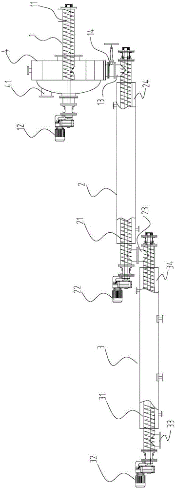
[0020] In the description of the present invention, it should be noted that the length direction of the continuous slagging system is the horizontal direction after installation; the terms "inner", "outer", "upper", "lower", "front", "back" etc The indicated orientation or positional relationship is based on figure 1 The positional relationship shown is only for the convenience of describing the present invention and simplifying the description, but does not indicate or imply that the referred device or element must have a specific orientation, be constructed and operated in a specific orientation, and therefore cannot be construed as limiting the present invention . In addition, the terms...


PUM


Abstract

The invention provides a continuous slag tapping system. The continuous slag tapping system comprises a reaction kettle slag extractor screwed outside a cracking device, wherein a slag tapping conveyer is arranged in the reaction kettle slag extractor, a sealed cabin is fixedly mounted outside a conveying tail end of the slag tapping conveyer, and a first slag hole is formed at the bottom of the sealed cabin; a primary slag extractor is fixedly connected with the tail end of the first slag hole, a second slag hole is formed at the bottom of the other end of the primary slag extractor, and a primary conveyer is arranged in the primary slag extractor; a secondary slag extractor is fixedly connected with the tail end of the second slag hole, a blanking hole is formed at the bottom of the other end of the secondary slag extractor, and a secondary conveyer is arranged in the secondary slag extractor; a primary water-cooling jacket is arranged in the primary slag extractor, and the primary water-cooling jacket is arranged around outside the primary conveyer; and a secondary water-cooling jacket is arranged in the secondary slag extractor, and the secondary water-cooling jacket is arranged around outside the secondary conveyer. The continuous slag tapping system can carry out slag tapping at high temperature without furnace shutdown after cracking, thus being more efficient.

Description

technical field [0001] The invention relates to a continuous slag discharging system for waste tires, waste plastics and reactors, in particular to an external rotation high-temperature continuous slag discharging device for pyrolysis of waste tires and waste plastics. Background technique [0002] At present, the slagging machine of the prior art has only one high-temperature reaction kettle. When working, the raw materials enter the reactor through the feeding device for cracking, and the cracked gas produced is collected as gasoline and diesel products after rectification. The residue produced by the cracking reaction remains in the reactor for accumulation. When the residue reaches a certain concentration and volume, it is necessary to stop heating, stop feeding, stop the reaction, and start the slag discharge system to remove the residue. Then the feed is added again, heated again, and the reaction starts. [0003] Because the process of slag discharge and reheating ...

Claims


Application Information

Patent Timeline
IPC IPC(8): C10G1/10C10B53/07
CPCC10B53/07C10G1/10C10G2300/1003Y02P20/143
Inventor 马宗臣肖焕清俆宗平毛文鹏
Owner 青岛伊克斯达智能装备有限公司
Features
  • R&D
  • Intellectual Property
  • Life Sciences
  • Materials
  • Tech Scout
  • Unparalleled Data Quality
  • Higher Quality Content
  • 60% Fewer Hallucinations
Learn More