
A front telescopic sleeve hydraulic cylinder for a dump truck

A telescopic, dump truck technology, applied in the field of hydraulic cylinders, can solve the problems of long maintenance man-hours, high manufacturing costs, difficult maintenance, etc., and achieve the effects of short maintenance man-hours, low manufacturing costs, and avoiding shaking or noise.

Active Publication Date: 2017-10-10
湖北万邦液压装备有限公司
View PDF8 Cites 0 Cited by
  • Summary
  • Abstract
  • Description
  • Claims
  • Application Information

AI Technical Summary

Problems solved by technology

[0004] However, the manufacturing cost of opening the annular groove and fitting the annular rubber ring on the support ring 2 is high
In addition, the welded part 3 of the outer cover does reciprocating motion for a long time, and it is difficult to maintain after the rubber ring is worn out. Replace the rubber ring
Long maintenance hours and high costs

Method used


Image

  • A front telescopic sleeve hydraulic cylinder for a dump truck
  • A front telescopic sleeve hydraulic cylinder for a dump truck
  • A front telescopic sleeve hydraulic cylinder for a dump truck

Examples


Embodiment 1

[0029] See Image 6 with Figure 7 As shown, the first embodiment of the present invention provides a front telescopic sleeve hydraulic cylinder for a dump truck, which includes a cylinder assembly 1 and an outer cover welded part 3. The outer cover welded part 3 has an opening at the front end, and the outer cover welded part The rear end of 3 is provided with an end cover 5, and the outer side wall of the outer cover welded part 3 is provided with an upper hinge shaft 4 near the front end; the cylinder barrel assembly 1 is inserted into the outer cover welded part 3 through the opening, and the cylinder barrel assembly The end of 1 passes through the end cover 5 and is locked by a large nut 6 located outside the end cover 5; the outer side wall of the cylinder assembly 1 is provided with a support ring 2, and the support ring 2 is equally provided with at least three support nails 7. The support nail 7 is slightly higher than the support ring. When the oil cylinder shakes, th...

Embodiment 2

[0032] See Image 6 with Figure 8 As shown, the structure of the second embodiment of the present invention is basically the same as that of the first embodiment. The difference is that the supporting nail 7 is a ball screw, and the ball screw includes a screw body 74, and a groove 73 is provided in the middle of the screw body 74. A spring 72 is installed in the groove 73, and a steel ball 71 is arranged on the end of the spring 72 close to the port of the groove 73. By setting the wave ball screw as a spring 72 and a steel ball 71 structure, the wave ball screw can be automatically expanded and contracted under the pressure of the cylinder assembly 1, avoiding the shaking or noise of the cylinder assembly 1 due to the gap. . In addition, since the friction relationship between the ball screw and the cylinder assembly 1 is rolling friction, compared with the existing sliding friction, it effectively reduces the friction between the ball screw and the cylinder assembly, and r...


PUM


Abstract

A front telescopic sleeve hydraulic cylinder for novel self-dumping trunk relates to the technical field of hydraulic cylinder. The front telescopic sleeve hydraulic cylinder for novel self-dumping trunk comprises a cylinder assembly and housing welded parts. The front end of the housing welded parts is provided an opening, and the rear end of the housing welded parts is provided with an end cap, and the lateral wall near the front end position of the housing welded parts is provided with an upper hinge axis. The cylinder assembly is inserted into the housing welded parts through the opening, and the end portion of the cylinder assembly is locked by a large nut outside the end cap after passing through the end cap. The lateral wall of the cylinder assembly is provided with a supporting ring which is evenly provided with at least three supporting nails. The front telescopic sleeve hydraulic cylinder for novel self-dumping trunk has the advantages of low manufacturing cost and short maintenance time.

Description

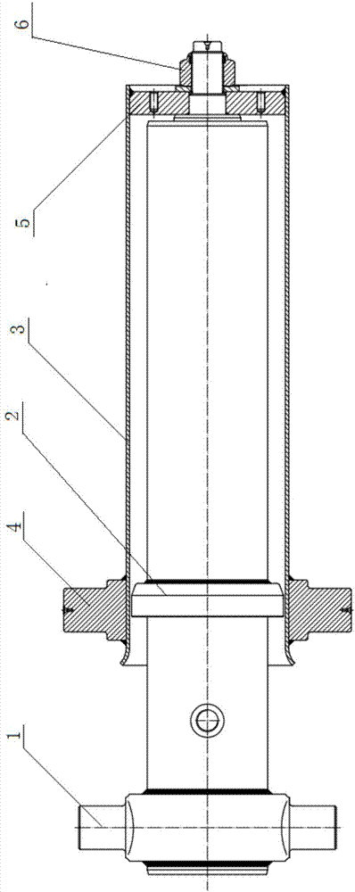
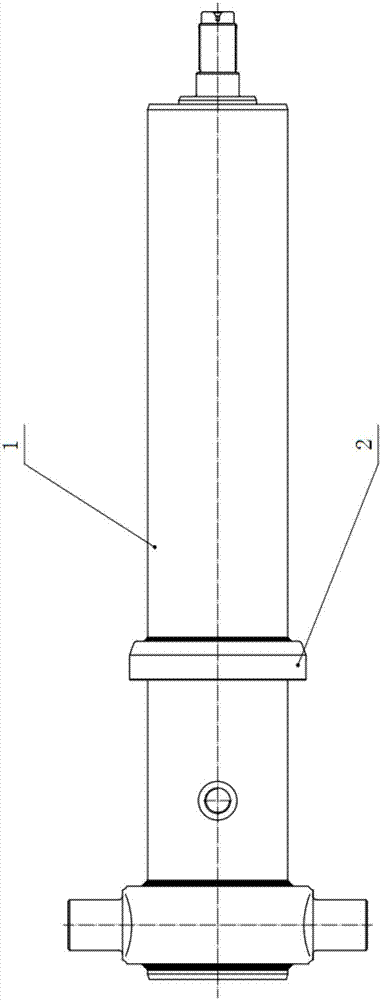
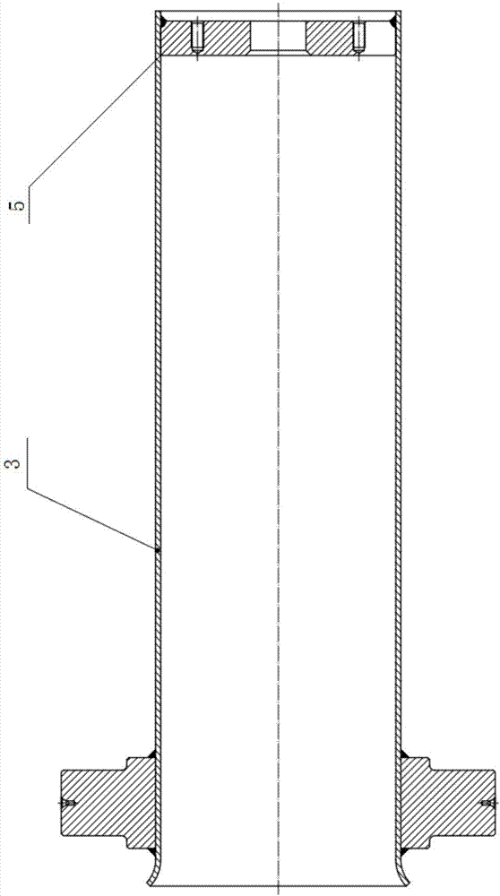
Technical field [0001] The invention relates to the technical field of hydraulic cylinders, in particular to a front telescopic sleeve hydraulic cylinder for dump trucks. Background technique [0002] At present, most of the lifting methods of dump trucks use front telescopic sleeve hydraulic cylinders, see Figure 1-4 As shown, the front telescopic sleeve hydraulic cylinder includes a cylinder barrel assembly 1 and an outer cover welded part 3, wherein the front end of the outer cover welded part 3 has an opening, and the rear end of the outer cover welded part 3 is provided with an end cover 5 , And the outer side wall of the outer cover welded part 3 is provided with an upper hinge shaft 4 near the front end; the cylinder barrel assembly 1 is inserted into the outer cover welded part 3 through the opening, and the end of the cylinder barrel assembly 1 passes through the end The cover 5 is locked by a large nut 6 located outside the end cover 5; the outer side wall of the cylind...

Claims


Application Information

Patent Timeline
Patent Type & Authority Patents(China)
IPC IPC(8): F15B15/14F15B15/20
CPCF15B15/1423F15B15/1428
Inventor 张建亮曹纯儒陈志斌雷献华钟琦
Owner 湖北万邦液压装备有限公司
Learn More