Compact ultrathin liquid crystal display backlight module structure and manufacturing method thereof
A backlight module, liquid crystal display technology, applied in the direction of light guide, optics, optical components, etc., to achieve the effect of shortening the production process, reducing the packaging cost, and reducing the manufacturing process
- Summary
- Abstract
- Description
- Claims
- Application Information
AI Technical Summary
Problems solved by technology
Method used
Image
Examples
Embodiment 1
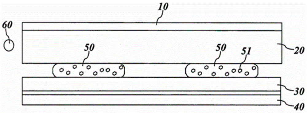
[0025] Such as figure 2 As shown, the structure of the compact and ultra-thin liquid crystal display (LCD / LED) backlight module of the present invention includes: an optical film set 10 , a light guide plate 20 , a reflection sheet 30 and a protective film 40 .
[0026] The optical film set 10 is used to allow the light to exit uniformly, and is disposed on the light exit surface of the light guide plate 20 . The light guide plate 20 is used to convert point light sources into surface light sources, and has a light emitting surface and a backlight surface opposite to the light emitting surface. The light emitted by the point light source is evenly emitted from the light-emitting surface. The light guide plate 20 of this embodiment is a toughened optical glass light guide plate with a thickness of 0.5-2.0 mm. The traditional acrylic light guide plate (3-5 mm) is replaced by an ultra-thin tempered optical glass plate and a thinner emission sheet is used. On the premise that t...
Embodiment 2
[0033] This embodiment provides a method for manufacturing an integrated structure of a light guide plate and a reflector, including the following steps:
[0034] (1) Peel off one side of the protective film on the 1 mm tempered optical glass with a double-sided protective film in a dust-free environment;
[0035] (2) Scrub the surface of the tempered optical glass with isopropanol to remove the protective film, and use an LED light bar to shine light on the tempered optical glass from the bottom to check for defects such as dirty spots and edge bursts;
[0036] (3) The UV light guide glue is printed on the surface of the 50 micron reflective film coil by screen printing technology according to the designed shading network, which can realize automatic roll-to-roll production;
[0037] (4) Curing the reflective film obtained in step (3) for 22 seconds at a UV wavelength of 390nm and a strength of 462.8mJ / cm2;
[0038] (5) Pass the side of the above-mentioned tempered optical gla...
Embodiment 3
[0040] This embodiment provides a method for manufacturing an integrated structure of a light guide plate and a reflector, including the following steps: (1) Peel off one side of the protective film on the 0.8mm tempered optical glass with double-sided protective film attached in a dust-free environment;
[0041] (2) Scrub the tempered optical glass with isopropanol to remove the protective film, and use an LED light bar to shine light on the tempered optical glass from the bottom to check for defects such as dirty spots and edge bursts;
[0042] (3) Print the UV light guide glue on the side of the tempered optical glass plate where the protective film is removed (as the backlight surface of the light guide plate) using screen printing technology according to the designed shading network;
[0043] (4) Curing the tempered optical glass plate obtained in step (3) for 21 seconds at a UV wavelength of 390nm and a strength of 486.5mJ / cm2;
[0044] (5) The side of the tempered optic...
PUM
| Property | Measurement | Unit |
|---|---|---|
| thickness | aaaaa | aaaaa |
| strength | aaaaa | aaaaa |
Abstract
Description
Claims
Application Information
 - R&D
- Intellectual Property
- Life Sciences
- Materials
- Tech Scout
- Unparalleled Data Quality
- Higher Quality Content
- 60% Fewer Hallucinations
Browse by: Latest US Patents, China's latest patents, Technical Efficacy Thesaurus, Application Domain, Technology Topic, Popular Technical Reports.
© 2025 PatSnap. All rights reserved.Legal|Privacy policy|Modern Slavery Act Transparency Statement|Sitemap|About US| Contact US: help@patsnap.com


