Magnetic induced light-dimming material, local backlight adjustment membrane, backlight module and display equipment

A backlight module and magnetic material technology, applied in optics, optical components, nonlinear optics, etc., can solve problems such as inability to perform accurate local backlight adjustment, inability to realize local backlight adjustment, and insufficient fineness of backlight partitions. Adjust the backlight in rows or columns, which is beneficial to the development and improves the display effect

Active Publication Date: 2017-01-25
HISENSE VISUAL TECH CO LTD
View PDF5 Cites 4 Cited by
  • Summary
  • Abstract
  • Description
  • Claims
  • Application Information

AI Technical Summary

Problems solved by technology

For direct-lit backlight modules, due to the limitation of LED size and control of LED switches, the backlight partitions are not fine enough to achieve accurate local backlight adjustment; for edge-lit backlight modules, since the light source is located in the backlight module The side of the group, so the backlight can only be partitioned in rows or columns (such as figure 1 shown) also cannot perform precise local backlight adjustment
In summary, accurate local backlight adjustment cannot be achieved by controlling the switch of the LED

Method used


Image

  • Magnetic induced light-dimming material, local backlight adjustment membrane, backlight module and display equipment
  • Magnetic induced light-dimming material, local backlight adjustment membrane, backlight module and display equipment
  • Magnetic induced light-dimming material, local backlight adjustment membrane, backlight module and display equipment

Examples


Embodiment 1

[0099] This embodiment provides a magnetic light-adjusting material using Dow Corning's SYLGARD184 two-component silicone rubber as the material of the transparent base and the elastic matrix of elastic bristles, and a local backlight adjustment film based on the magnetic light-adjusting material.

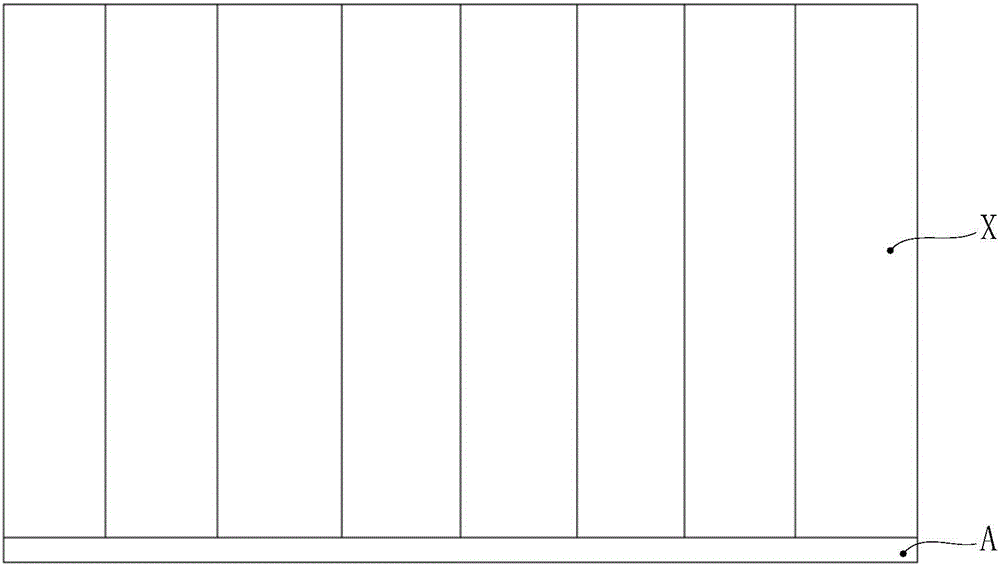
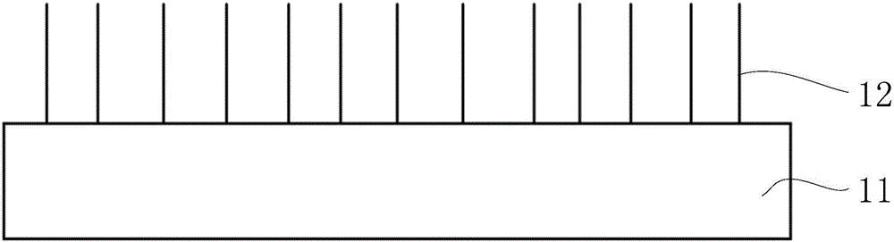
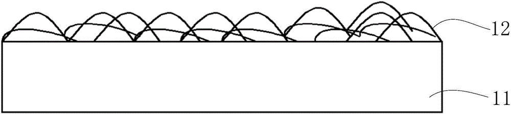
[0100] In the magnetic dimming material provided in this embodiment, the elastic bristles in the bristle array are cylinders with a diameter of 400 μm and a length of 1 mm, the distance between the elastic bristles is 200 μm, and the opaque magnetic material is nickel.

[0101] In this embodiment, vacuum injection molding is adopted to prepare the above-mentioned magneto-sensitive dimming material, and the specific steps include:

[0102] Firstly, it is determined to process the polytetrafluoroethylene cathode mold according to the parameters such as the size and spacing of the above-mentioned elastic bristles, and the mold surface is coated with a release agent; then the basic comp...

Embodiment 2

[0106] This embodiment provides a magnetic light-adjusting material using Dow Corning's SYLGARD184 two-component silicone rubber as the material of the transparent base and the elastic matrix of elastic bristles, and a local backlight adjustment film based on the magnetic light-adjusting material.

[0107] In the magnetic dimming material provided in this embodiment, the elastic bristles in the bristle array are cylinders with a diameter of 0.5 μm and a length of 40 μm, the distance between the elastic bristles is 10 μm, and the opaque magnetic material is nickel.

[0108] In this embodiment, vacuum injection molding is adopted to prepare the above-mentioned magneto-sensitive dimming material, and the specific steps include:

[0109] First of all, it is determined to process the polytetrafluoroethylene cathode mold according to the parameters such as the size and spacing of the above-mentioned elastic bristles, and the mold surface is coated with a release agent; then the basic...

Embodiment 3

[0113] This embodiment provides a magnetic light-adjusting material using Dow Corning's SYLGARD184 two-component silicone rubber as the material of the transparent base and the elastic matrix of elastic bristles, and a local backlight adjustment film based on the magnetic light-adjusting material.

[0114] In the magnetic dimming material provided in this embodiment, the elastic bristles in the bristle array are cylinders with a diameter of 1 mm and a length of 10 mm, the distance between the elastic bristles is 500 μm, and the opaque magnetic material is trioxide with a particle size of 10 μm. Iron (Fe 3 o 4 ).

[0115] In this embodiment, vacuum injection molding is adopted to prepare the above-mentioned magneto-sensitive dimming material, and the specific steps include:

[0116] First of all, it is determined to process the polytetrafluoroethylene cathode mold according to the parameters such as the size and spacing of the above-mentioned elastic bristles, and the mold su...


PUM

PropertyMeasurementUnit
lengthaaaaaaaaaa
diameteraaaaaaaaaa
diameteraaaaaaaaaa

Abstract

The invention discloses a magnetic induced light-dimming material, a local backlight adjustment membrane, a backlight module and display equipment and belongs to the technical field of liquid crystal display. The magnetic induced light-dimming material comprises a transparent substrate and a seta array which is distributed on the surface of the transparent substrate and formed by non-transparent, magnetic and elastic setae; shapes of the elastic setae relative to the transparent substrate can be changed between an upright state and a state of being attached to the surface of the transparent substrate under the control of an external magnetic field. The magnetic induced light-dimming material forms a magnetic induced light-dimming layer, and multiple electromagnetic units controlled by virtue of a micro circuit are arranged on the magnetic induced light-dimming layer, so that the local backlight adjustment membrane is obtained, each electromagnetic unit independently controls the shapes of the elastic setae in a preset region, corresponding to the electromagnetic unit, of the magnetic induced light-dimming layer to realize control of light transmittances of different regions of the magnetic induced light-dimming layer, and further local backlight adjustment is realized. Accurate local backlight adjustment can be realized by utilizing the magnetic induced light-dimming material.

Description

technical field [0001] The invention relates to the technical field of liquid crystal display, in particular to a magnetic light-adjusting material, a local backlight adjustment film, a backlight module and a display device. Background technique [0002] With the continuous development of liquid crystal display technology, people have higher and higher requirements for the display effect of liquid crystal display devices, and the research and development of methods for improving the display effect of liquid crystal display devices has become the focus of the development of liquid crystal display devices. Among various methods for improving the display effect of a liquid crystal display device, the Local Dimming (local backlight adjustment) technology has attracted widespread attention due to its easy implementation and obvious effect. [0003] The existing Local Dimming technology is realized by using a large number of LEDs (Light Emitting Diodes, Light Emitting Diodes) to f...

Claims


Application Information

Patent Timeline
Patent Type & Authority Applications(China)
IPC IPC(8): G02B26/02G02F1/1335G02F1/13357G09G3/34
CPCG02B26/02G02F1/1335G02F1/1336G09G3/342G02F1/133607
Inventor 刘振国李富琳宋志成
Owner HISENSE VISUAL TECH CO LTD
Why Eureka
Try Eureka