SOT26 test clamp with adjustable test groove and operation method thereof

A SOT26, adjustable technology, applied in the direction of semiconductor/solid-state device testing/measurement, electrical components, circuits, etc., can solve the problem of SOT26 pin left and right deviation, so as to improve the average yield rate of testing, increase production capacity, and improve yield rate Effect

Active Publication Date: 2017-01-25
CHANGJIANG ELECTRONICS TECH CHUZHOU
View PDF4 Cites 2 Cited by
  • Summary
  • Abstract
  • Description
  • Claims
  • Application Information

AI Technical Summary

Problems solved by technology

[0006] Aiming at the problem in the prior art that the SOT26 pins deviate left and right when contacting the test piece during the SOT26 test, the present invention provides a SOT26 test clip with adjustable test groove and its operation method

Method used


Image

  • SOT26 test clamp with adjustable test groove and operation method thereof
  • SOT26 test clamp with adjustable test groove and operation method thereof
  • SOT26 test clamp with adjustable test groove and operation method thereof

Examples


Embodiment 1

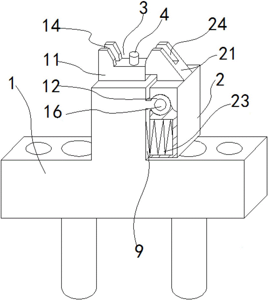
[0050] The test groove adjustable SOT26 test clip of this embodiment includes a fixed clip 1 and a movable clip 2; the fixed clip 1 and the movable clip 2 are connected by a rotating device that cooperates with each other, such as Figure 5 , 7 As shown, the rotating device is a convex semi-cylinder 12 and a concave semi-cylindrical 22 respectively arranged on the respective sides facing the fixed clip 1 and the movable clip 2 and cooperatingly arranged; On the convex semi-cylindrical 12, the concave semi-cylindrical 22 rotates around the convex semi-cylindrical 12. It is realized that the jaw of the test clip can be adaptively adjusted according to the size of the SOT26, thereby achieving the purpose of improving the average yield rate of the SOT26 test. Due to the small overall size of SOT26, there is no need to realize a large width adjustment, as long as a small gap is reserved between the fixed clip 1 and the movable clip 2, the required width adjustment of the jaw 3 can...

Embodiment 2

[0052] The test groove adjustable SOT26 test clip of this embodiment has the same basic structure as that of Embodiment 1, the differences and improvements are as follows: figure 1 As shown, the fixed clamp 1 is in the shape of an inverted "T"; the movable clamp 2 is hung on one side of the middle boss of the fixed clamp 1, and an "L"-shaped rotation gap 9 is left between the fixed clamp 1 and the fixed clamp 1. , the gap is "L"-shaped, which realizes the small-angle rotation of the concave semi-cylinder 22 with the convex semi-cylindrical 12 as the axis. Such as Figure 6 As shown, the lower half of the movable clamp 2, the lower part of the concave half cylinder 22 is provided with a horizontal spring chamber 25, and a horizontal jaw width adjustment spring 23 is built in. After the SOT26 test is completed, the width of the jaw 3 can be reset, and the clamping force of the jaw 3 to the SOT26 can be realized during the test, so as to ensure the stability of the position dur...

Embodiment 3

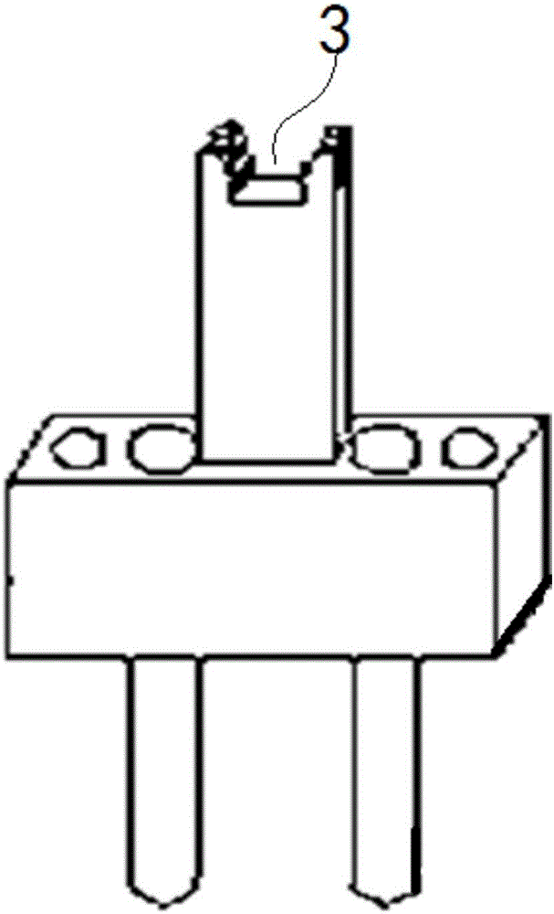
[0054] The test groove adjustable SOT26 test clip of this embodiment has the same basic structure as that of Embodiment 2, the differences and improvements are as follows: Figure 5 As shown, a vertical ejector rod chamber 15 is arranged inside the boss of the middle part of the fixing clip 1, and the ejector rod spring and the ejector rod 4 connected to each other are built in from bottom to top; as Figure 10 As shown, the ejector rod 4 is in a "convex" shape, the top end passes through the upper surface of the fixing clip 1, near the middle of the jaw 3, and the bottom is the ejector rod seat 41 connected to the ejector rod spring, so as to ensure that the SOT26 product is not tested after the test is completed. It will be stuck in the test clip, thereby reducing the probability of overlapping alarms on the auxiliary plate. The upper surface of the fixed clip 1 is provided with a fixed clip finger 11, and the upper surface of the movable clip 2 is provided with a movable cl...


PUM


Abstract

The invention discloses a SOT26 test clamp with an adjustable test groove and an operation method thereof and belongs to the technical field of chip test. The SOT26 test clamp with the adjustable test groove provided by the invention comprises a fixed clamp and a moveable clamp, wherein the fixed clamp and the moveable clamp are connected through mutually matched rotating devices; the width adjustment of a clamp rim between the fixed clamp and the moveable clamp can be realized through the rotation of the moveable clamp relative to the fixed clamp; the clamp rim of the test clamp can be adaptively adjusted according to the size of SOT26. The operation method for the test clamp provided by the invention comprises the steps of pressing in SOT26, testing and pushing out; a spring is utilized to control the opening and closing of the moveable clamp, so that the left and right shifting caused by the size of SOT26 can be made up and the yield of once test can be increased; a jacking rod is additionally arranged; under the synergic effect of the moveable clamp and the jacking rod, the purposes of accurately positioning SOT26 in a test process, preventing the material overlapping and increasing the test yield can be achieved; equivalently, the capacity is promoted, so that the effect of double benefit can be achieved.

Description

technical field [0001] The invention relates to the technical field of chip testing, in particular to an SOT26 test clip with an adjustable test groove and an operating method thereof. Background technique [0002] At present, in the semiconductor integrated circuit manufacturing process, it is necessary to further test the finished chip after cutting and packaging, and the test fixture plays a key role. During the chip testing process, the specific method is to transfer the chip to the test clip through the suction nozzle of the chip sorter. After the test is completed, the suction nozzle of the chip sorter transfers the chip to the next process. [0003] SOT is the abbreviation of English Small-outlinetransistor, which refers to a transistor packaging form, SOT26 is the abbreviation of SOT23-6, SOT23-6 is a kind of SOT23, the mantissa 6 means 6 pins; the original equipment design test clips such as figure 2 As shown, the opening size of the clamp (3) is fixed, and the le...

Claims


Application Information

Patent Timeline
Patent Type & Authority Applications(China)
IPC IPC(8): H01L21/66
CPCH01L22/14
Inventor 李国祥吴靖宇叶金锋蒋节文孙超
Owner CHANGJIANG ELECTRONICS TECH CHUZHOU
Why Eureka
Try Eureka