General short needle and micro needle clamp

A micro-needle and fixture technology, applied in electronic circuit testing, measuring devices, instruments, etc., can solve the problems of not very optimized design, slow testing speed, and high production cost, and achieve simple and reasonable structural design, saving production costs, and improving testing. The effect of precision

Inactive Publication Date: 2016-03-23
HANS LASER TECH IND GRP CO LTD +1
View PDF9 Cites 4 Cited by
  • Summary
  • Abstract
  • Description
  • Claims
  • Application Information

AI Technical Summary

Problems solved by technology

[0003] At present, the design of the general-purpose short needle fixture structure is not very optimized, and the fixture structure cannot use steel needles with a diameter less than 0.15mm
However, for some small pads below 0.12mm, high-density general-purpose boards cannot be tested. Only the micro-needle fixtures used by high-precision machines can test such boards. Small area, limited points, slow test speed, high production cost, and inconvenient for users to use

Method used


Image

  • General short needle and micro needle clamp
  • General short needle and micro needle clamp

Examples


Embodiment Construction

[0043] In order to make the purpose, technical solution and advantages of the present invention clearer, the general short needle and microneedle jig of the present invention will be further described in detail through the following examples and in conjunction with the accompanying drawings. It should be understood that the specific embodiments described here are only used to explain the present invention, not to limit the present invention.

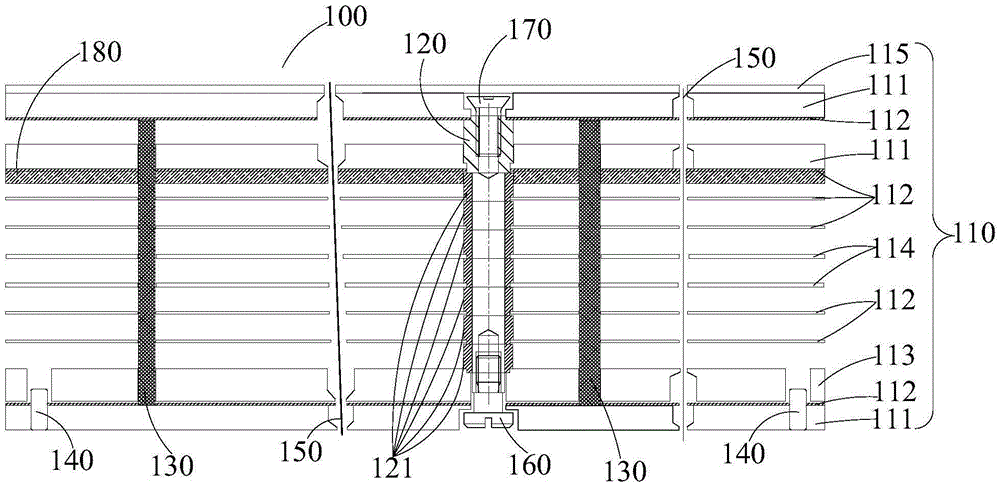
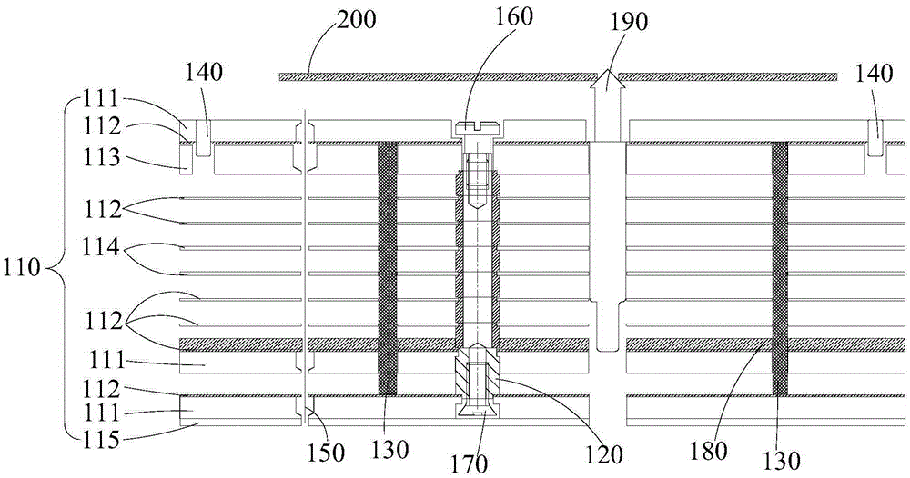
[0044] see figure 1 and figure 2 , the universal short needle and microneedle jig 100 according to an embodiment of the present invention includes a composite fiber board 110 , a fixed copper post 120 , a steel needle 150 and a sponge 180 .

[0045] In the present invention, the composite fiber board 110 is provided with a through hole for installing the fixed copper column 120, and the fixed copper column 120 is installed in the through hole. The fixed copper column 120 is covered with a plurality of partition blocks 121, and each pa...


PUM

PropertyMeasurementUnit
diameteraaaaaaaaaa
diameteraaaaaaaaaa
thicknessaaaaaaaaaa

Abstract

The invention provides a general short needle and micro needle clamp. The general short needle and micro needle clamp comprises a composite fiber board in a multi-layer structure, fixing copper columns, steel needles and sponge, wherein the composite fiber board comprises a top fiber board, a middle fiber board and a lower fiber board which are sequentially laminated, the top fiber board, the middle fiber board and the lower fiber board each comprise multi-layer fiber boards, a preset gap is further arranged between two adjacent fiber boards, a preset gap scope is 0.01-4mm, the composite fiber boards are each provided with through holes and penetration needle holes, the fixing copper columns are arranged in the through holes, the steel needles are mounted in the needle holes, two ends of the steel needles are respectively exposed out of surfaces of the fiber boards, diameters of the steel needles are greater than or equal to 0.08mm, the sponge is arranged on the surface of one of the fiber boards, so the steel needles are not easy to generate deformation when the steel needles having relatively small diameters are utilized to test, the loss rate is reduced, the test yield of the clamp is improved, and thereby detection on PCBs with smaller bonding pads are convenient for users.

Description

technical field [0001] The invention relates to the technical field of PCB measuring fixtures, in particular to a universal short needle and microneedle fixture. Background technique [0002] PCB board, the Chinese name is printed circuit board, which is the carrier for the installation of electronic components and the provider of the electrical connection of electronic components. Therefore, the PCB board is a very important electronic component. In order to ensure that the quality of products using PCB boards is absolutely guaranteed, the testing work after the PCB board is manufactured is very important. [0003] At present, the design of the general-purpose short needle fixture structure is not very optimized, and the fixture structure cannot use steel needles with a diameter less than 0.15mm. However, for some small pads below 0.12mm, high-density general-purpose boards cannot be tested. Only the micro-needle fixtures used by high-precision machines can test such board...

Claims


Application Information

Patent Timeline
Patent Type & Authority Applications(China)
IPC IPC(8): G01R1/04G01R31/28
CPCG01R31/2808G01R1/0425
Inventor 易博谭周强杨慧萍董文利高云峰
Owner HANS LASER TECH IND GRP CO LTD
Why Eureka
Try Eureka