
Foot platform structure of game equipment

A technology of platform structure and game equipment, applied in the field of game platform device and pedal platform structure, can solve the problems of difficult disassembly and assembly of the pedal platform, increased overall size of the platform, uneven force on the output shaft, etc. The effect of small force change and uniform force on the shaft

Pending Publication Date: 2017-02-01
GUANGZHOU ZHUOYUAN VIRTUAL REALITY TECH CO LTD
View PDF6 Cites 3 Cited by
  • Summary
  • Abstract
  • Description
  • Claims
  • Application Information

AI Technical Summary

Problems solved by technology

[0002] At present, the structure of the movable pedal platform commonly used in game equipment on the market is generally two degrees of freedom. Most of them adopt the crank arm transmission structure, the structure is relatively complicated, the copper sleeves of the structural joints are easy to wear, and the overall carrying capacity of the platform is limited by the fisheye bearing. If the fish-eye bearing is increased, the overall size of the platform will also be increased, so the size of the platform is also limited by the fish-eye bearing; on the other hand, the pedal platform is not easy to disassemble and assemble, which takes time and effort; more importantly , when the crank arm transmission structure is working, the force of the platform acting on the output shaft changes complicatedly, which makes the output shaft prone to uneven force, and the crank arm transmission structure is mostly cantilevered at the position of the output shaft, which has a relatively large impact on the output shaft. The large bending moment leads to a larger shaft diameter of the output shaft to meet the structural requirements

Method used


Image

  • Foot platform structure of game equipment
  • Foot platform structure of game equipment
  • Foot platform structure of game equipment

Examples


Embodiment Construction

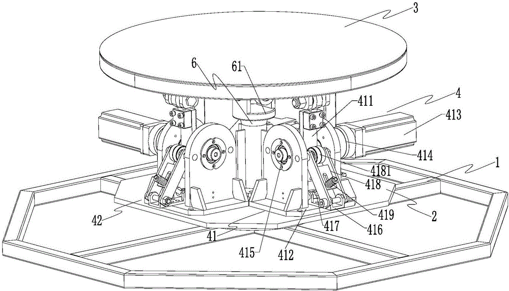
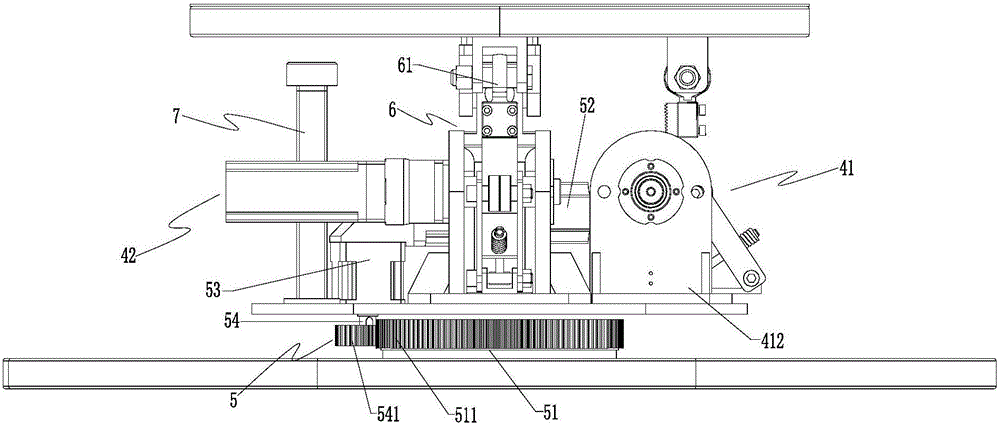
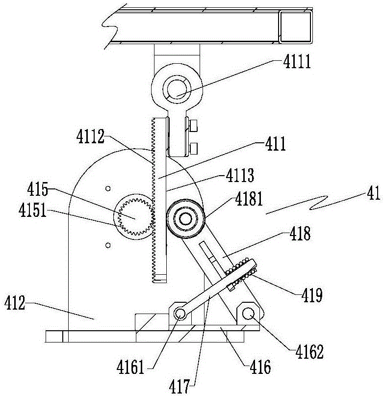
[0019] Such as Figures 1 to 3 As shown, the foot platform structure of a game device according to the present invention includes a base 1, a slewing support 2 above the base, a foot platform 3 above the slewing support, and a slewing support and a foot pedal. The two-degree-of-freedom rack transmission part 4 between the platforms, wherein the slewing support 2 is rotatably set on the base 1 through the slewing assembly 5, and the pedal platform 3 is movably set on the slewing support 2 through a universal joint pillar 6 Above, the two-degree-of-freedom rack transmission component 4 includes a first rack transmission assembly 41 and a second rack transmission assembly 42 with the same structure.

[0020] The above-mentioned first rack transmission assembly 41 and the second rack transmission assembly 42 have the same structure, and the first rack transmission assembly 41 is used as an example for illustration. The first rack transmission assembly 41 respectively includes The...


PUM


Abstract

The invention discloses a foot platform structure of game equipment. The foot platform structure comprises a base, a rotary pedestal arranged above the base, a foot platform arranged above the rotary pedestal and a two-degree-of-freedom rack transmission assembly arranged between the rotary pedestal and the foot platform, wherein the rotary pedestal is rotationally arranged on the base through a rotary component; the foot platform is movably arranged on the rotary pedestal through a universal joint pillar; the two-degree-of-freedom rack transmission assembly comprises a first rack transmission component and a second rack transmission component which have the same structure; and each rack transmission component comprises a rack plate which is movably arranged at the bottom of the foot platform, a servo motor mechanism which is fixedly arranged at the upper part of the rotary pedestal and is in meshing and transmission matching with the corresponding rack plate, and a compaction mechanism which is matched with the corresponding rack plate in a butting-pressing manner and ensures the corresponding rack plate to tend to be in transmission matching with the corresponding servo motor mechanism. According to the foot platform structure, with adoption of a novel rack plate transmission structure, the foot platform structure is simple in structure, convenient to disassemble and assemble, not liable in abrasion, durable and reliable; and in addition, with adoption of a structure mode of supporting a gear shaft by two points, stress of the gear shaft is a torque basically, and thus the diameter of the gear shaft and stress variation on the shaft are small, stress is uniform, and the foot platform structure is safe and stable.

Description

technical field [0001] The invention relates to a game platform device, which belongs to the technical field of game equipment, in particular to a pedal platform structure of the game equipment. Background technique [0002] At present, the structure of the movable pedal platform commonly used in game equipment on the market is generally two degrees of freedom. Most of them adopt the crank arm transmission structure, the structure is relatively complicated, the copper sleeves at the joint positions of the structure are easy to wear, and the overall carrying capacity of the platform is limited by the fisheye bearing. If the fisheye bearing is increased, the overall size of the platform will also be increased, so the size of the platform is also limited by the fisheye bearing; on the other hand, the pedal platform is not easy to disassemble and assemble, which takes time and effort; more importantly , when the crank arm transmission structure is working, the force of the platf...

Claims


Application Information

Patent Timeline
Patent Type & Authority Applications(China)
IPC IPC(8): A63F13/90A63G31/00
CPCA63F13/90A63G31/00
Inventor 赖家斌秦华军
Owner GUANGZHOU ZHUOYUAN VIRTUAL REALITY TECH CO LTD
Learn More