Extremely low concentration extraction apparatus

An extraction equipment and concentration technology, applied in the field of extremely low concentration extraction equipment, can solve the problems of high shear force of solution, high power consumption, small shear force, etc., and achieve good effect, improve reaction effect, and improve the effect of reaction speed.

Active Publication Date: 2017-02-01
山东京阳科技股份有限公司
View PDF2 Cites 5 Cited by
  • Summary
  • Abstract
  • Description
  • Claims
  • Application Information

AI Technical Summary

Problems solved by technology

[0010] In order to overcome the disadvantages of high power consumption, high shearing force on solution, and unfavorable maintenance of the activity of biomacromolecules in the prior art, the technical problem to be solved by the present invention is to provide a low power consumption, high shearing force on solution Very low-concentration extraction equipment with low shear force and good for maintaining the activity of biomacromolecules

Method used


Image

  • Extremely low concentration extraction apparatus
  • Extremely low concentration extraction apparatus
  • Extremely low concentration extraction apparatus

Examples


Embodiment 1

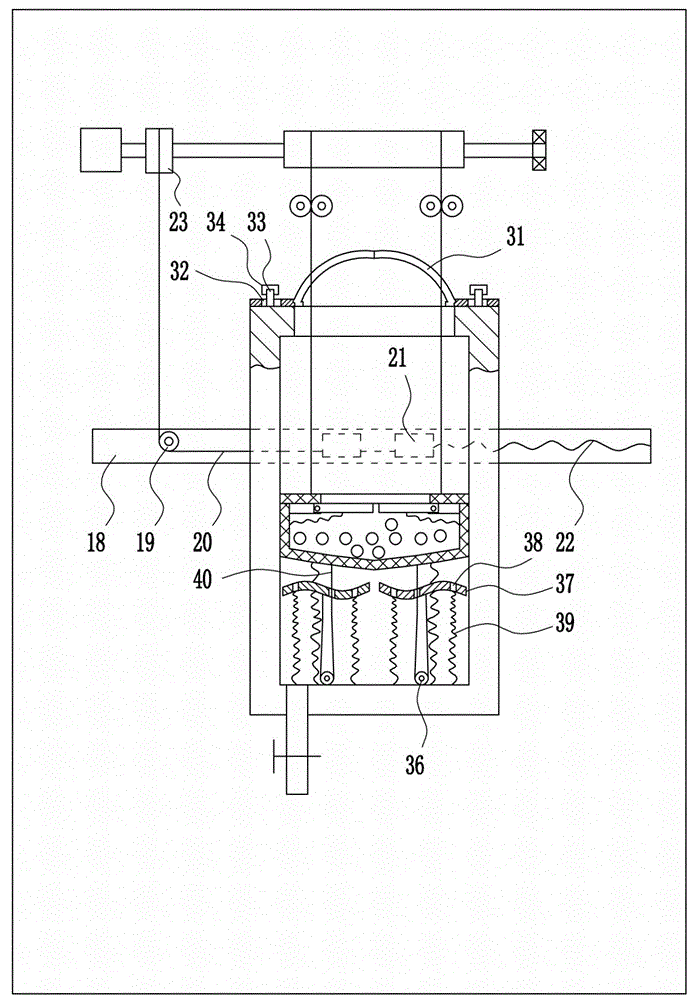
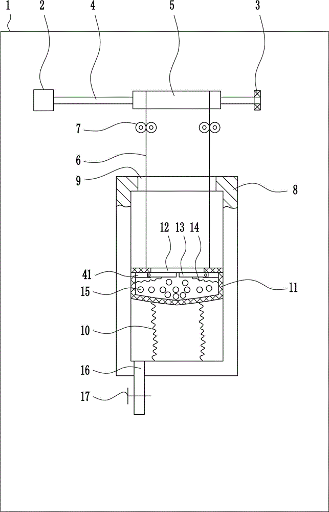
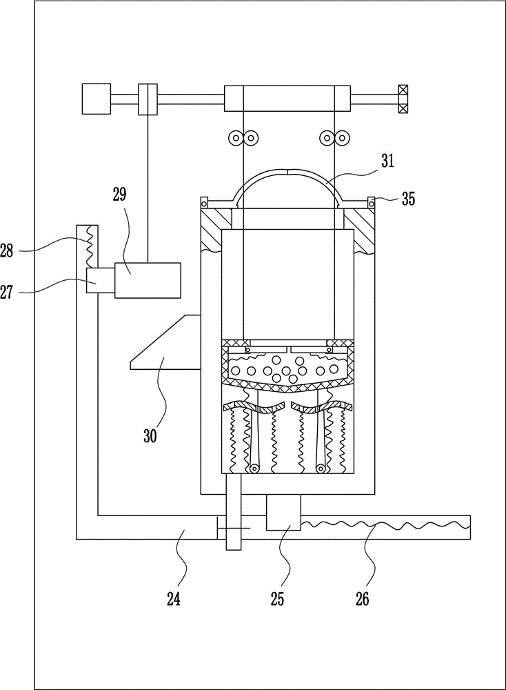
[0036] A very low concentration extraction device such as Figure 1-3 As shown, it includes a fixed plate 1, a motor 2, a bearing seat 3, a rotating rod 4, a drum 5, a first wire rope 6, a first guide wheel 7, an extraction box 8, a first spring 10, a screen frame 11, a first Baffle plate 13, second spring 14, small ball 15, liquid outlet pipe 16, electric control valve 17 and mounting plate 41, fixed plate 1 upper front left side is connected with motor 2 by the mode of bolt connection, on the output shaft of motor 2 The rotating rod 4 is connected through the coupling, and the upper front right side of the fixed plate 1 is connected with the bearing seat 3 through bolt connection, the rotating rod 4 passes through the bearing seat 3, and the rotating rod 4 is connected with the bearing seat 3 through an interference connection. The inner bearing is connected, the rotating rod 4 is connected with a drum 5 through a surplus connection, the first steel wire rope 6 is wound on t...

Embodiment 2

[0044] A very low concentration extraction device such as Figure 1-3As shown, it includes a fixed plate 1, a motor 2, a bearing seat 3, a rotating rod 4, a drum 5, a first wire rope 6, a first guide wheel 7, an extraction box 8, a first spring 10, a screen frame 11, a first Baffle plate 13, second spring 14, small ball 15, liquid outlet pipe 16, electric control valve 17 and mounting plate 41, fixed plate 1 upper front left side is connected with motor 2 by the mode of bolt connection, on the output shaft of motor 2 The rotating rod 4 is connected through the coupling, and the upper front right side of the fixed plate 1 is connected with the bearing seat 3 through bolt connection, the rotating rod 4 passes through the bearing seat 3, and the rotating rod 4 is connected with the bearing seat 3 through an interference connection. The inner bearing is connected, the rotating rod 4 is connected with a drum 5 through a surplus connection, the first steel wire rope 6 is wound on th...


PUM


Abstract

The invention relates to an extraction apparatus, in particular to an extremely low concentration extraction apparatus. The technical problem to be solved by the present invention is to provide an extremely low concentration extraction apparatus which is low in power consumption, has little shear force to solution and is advantageous for maintaining the activity of biological macromolecules. In order to solve the above technical problems, the present invention provides the extremely low concentration extraction apparatus comprising a fixing plate, a motor, a bearing seat, a rotary rod, a drum, a first wire rope, a first guide wheel, an extraction tank, a first spring, a filter frame, the first baffle, etc. The left side of the upper front of the fixing plate is connected to the motor, and the output shaft of the motor is connected with the rotary rod through a coupling rod. The extremely low concentration extraction apparatus utilizes small balls with extractant attached to achieve a lower concentration of extraction of the solution to be extracted, so that not only the extraction work can be successfully completed, but also the shear strength of the solution can be effectively reduced.

Description

technical field [0001] The invention relates to an extraction device, in particular to an extremely low-concentration extraction device. Background technique [0002] Solvent extraction, referred to as extraction, is an important development branch of current green chemistry. It is a mass transfer separation process in which a liquid extractant is used to treat immiscible two-component or multi-component solutions to achieve component separation. The extraction technology can choose the appropriate extraction system and process according to the separation object and process requirements, which has the characteristics of high selectivity, good separation effect, easy operation and strong adaptability. With the wide application of extraction in atomic energy chemical industry, hydrometallurgy and petrochemical industry, the scale of production is expanding day by day, and higher and higher requirements are put forward for extraction equipment. In the past 30 years, extraction...

Claims


Application Information

Patent Timeline
Patent Type & Authority Applications(China)
IPC IPC(8): B01D11/04
CPCB01D11/04
Inventor 不公告发明人
Owner 山东京阳科技股份有限公司
Why Eureka
Try Eureka