Rotary-ring mill

A mill and mill technology, applied in grain processing and other directions, can solve the problems of large vibration, short life of wearing parts, and high energy consumption, and achieve the effects of reducing noise and vibration, preventing direct contact, and high fineness of finished products.

Active Publication Date: 2017-02-01
HENAN LIMING HEAVY IND SCI & TECH
View PDF5 Cites 2 Cited by
  • Summary
  • Abstract
  • Description
  • Claims
  • Application Information

AI Technical Summary

Problems solved by technology

Raymond mill is suitable for coarse powder processing. In structure, the grinding roller rotates, the grinding ring does not move, and the roller sleeve rotates. The pressure between the grinding roller and the grinding ring is realized by the centrifugal force generated by the grinding roller rotation. The grinding roller and the grinding ring are directly connected. Contact, the material layer throws the material through the spatula; its disadvantages are large noise, large vibration, high energy consumption, short life of wearing parts, and it cannot be used for ultrafine powder processing
The micropowder mill is suitable for ultrafine powder processing. The structure is also that the grinding ring does not move while the grinding roller rotates. The roller sleeve rotates. The pressure between the grinding roller and the grinding ring is also realized by the centrifugal force generated by the rotation of the grinding roller. The grinding roller and the grinding The ring is in direct contact, which is different from the Raymond mill in that the grinding ring is a multi-layer grinding roller table, and the grinding rollers are connected in series with multi-layer roller sleeves; the disadvantages are large noise, large vibration, high energy consumption, and cannot be used for coarse powder processing , Short service life of wearing parts
The vertical mill is suitable for large-scale powder processing. The structure is that the grinding disc rotates, the grinding roller does not move, and the roller sleeve rotates. The pressure of the grinding roller is realized by the grinding roller pressure device. The principle of layer grinding is used for grinding; the disadvantage is that the manufacturing cost is high, the shape is large, and it is not suitable for miniaturized grinding production

Method used


Image

  • Rotary-ring mill
  • Rotary-ring mill
  • Rotary-ring mill

Examples


Embodiment Construction

[0022] The embodiments of the present invention will be described in detail below in conjunction with the accompanying drawings. This embodiment is implemented on the premise of the technical solution of the present invention, and detailed implementation methods and specific operating procedures are provided, but the scope of protection of the present invention is not limited to the following Described embodiment.

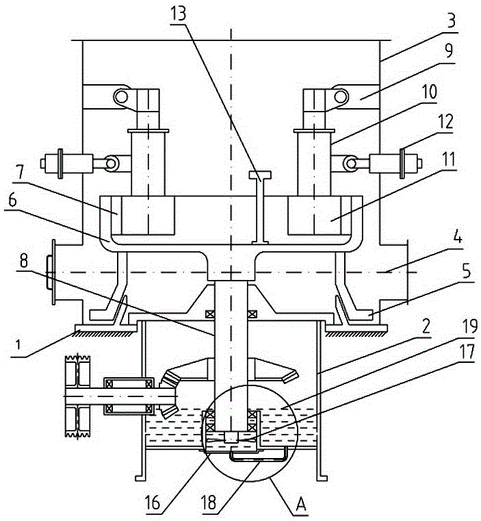
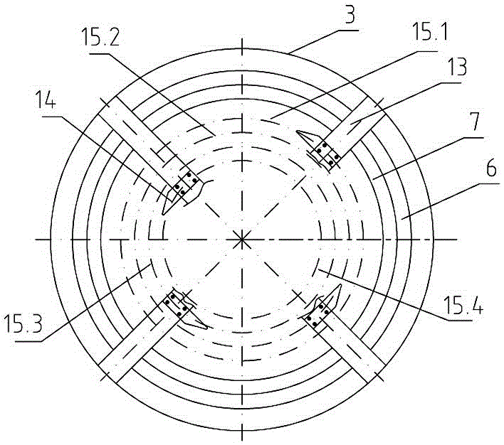
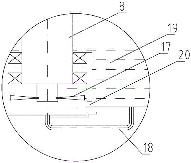
[0023] Such as Figure 1-5 As shown, the rotary ring mill of the present invention includes a vertical reducer gearbox 2 arranged on the machine base 1, a mill housing 3 arranged on the vertical reducer gearbox 2 and the top of the machine base 1 , the bottom of the inner cavity of the mill housing 3 is provided with an air duct and a scraper device 5, and a milling unit is arranged in the mill housing 3 above the air duct; the milling unit includes a bowl-shaped grinding disc 6 provided on the upper opening, The inner ring wall of the bowl-shaped grinding disc 6 ...


PUM


Abstract

The invention discloses a rotary-ring mill. The rotary-ring pulverizer mill comprises a mill shell arranged at the top of a vertical reducer gearbox, wherein an air duct and a scraping device are arranged at the bottom of the mill shell, and a milling unit is arranged in the mill shell which is located above the air duct and the scraping device; the milling unit comprises a bowl-shaped milling disc provided with an upper opening, a milling ring is fixedly connected to the inner ring wall of the bowl-shaped milling disc, at least two milling roll mechanisms are uniformly distributed and fixed on the inner sidewall of the mill shell which is located above the bowl-shaped milling disc along a peripheral direction, and each milling roll mechanism is composed of a suspension arm fixed on the inner sidewall of the mill shell, a milling roll hinged and hung on the suspension arm and a milling roll sleeve rotatably sleeving the milling roll; a milling roll pressing limit mechanism is arranged on the sidewall of the mill shell and at a position corresponding to each milling roll; and a lubricant oil circulation device is arranged on the bottom wall of the vertical reducer gearbox. The rotary-ring pulverizer mill disclosed by the invention has the following advantage: the central axis of the milling ring is parallel to the axis of a power output shaft, and a kinematic pair bearing a great axial force, and related mechanisms are omitted.

Description

technical field [0001] The present invention relates to milling equipment, in particular to a rotary ring mill. Background technique [0002] At present, commonly used grinding equipment are Raymond mill, micropowder mill, vertical mill and so on. Raymond mill is suitable for coarse powder processing. In structure, the grinding roller rotates, the grinding ring does not move, and the roller sleeve rotates. The pressure between the grinding roller and the grinding ring is realized by the centrifugal force generated by the grinding roller rotation. The grinding roller and the grinding ring are directly connected. Contact, the material layer throws the material through the spatula; its disadvantages are large noise, large vibration, high energy consumption, short life of wearing parts, and it cannot be used for ultrafine powder processing. The micropowder mill is suitable for ultrafine powder processing. The structure is also that the grinding ring does not move while the grin...

Claims


Application Information

Patent Timeline
Patent Type & Authority Applications(China)
IPC IPC(8): B02C15/08B02C23/20B02C23/00
CPCB02C15/003B02C15/08B02C23/00B02C23/20B02C2015/008
Inventor 白英辉孔金山刘守胜张伟伟丁成坤王喜昌刘靖徐小定
Owner HENAN LIMING HEAVY IND SCI & TECH
Why Eureka
Try Eureka