
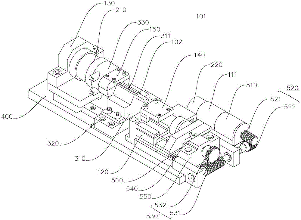
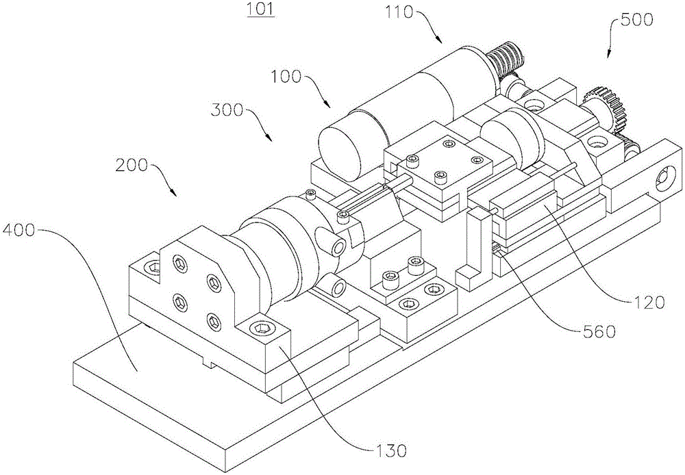
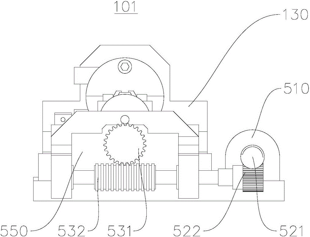
In-situ tension and compression testing platform and observation system

A test platform and in-situ technology, applied in the direction of applying stable tension/pressure to test the strength of materials, can solve problems such as imperfections, size limitations, and inability to integrate thermal field devices, and achieve good compatibility, compact size, and testing high precision effect

Pending Publication Date: 2017-02-01
YANCHENG INST OF TECH
View PDF6 Cites 7 Cited by
  • Summary
  • Abstract
  • Description
  • Claims
  • Application Information

AI Technical Summary

Problems solved by technology

[0003] In the category of many micro-nano mechanical parameter tests, the mechanical parameters related to tension and compression loads are important mechanical properties of materials, but the field of in-situ tension and compression tests under the action of mechanical and thermal coupling is not perfect at present, and the specific performance is as follows: Due to the size limitation of microscopic equipment, most of the current research is focused on the simple in-situ micro-nano tension and compression test of extremely small structures such as nanometer and thin film materials based on the micro / nano electromechanical system technology. In situ tensile and compressive tests on the scale above), due to the existence of the size effect, these studies have great limitations
Due to the immature development of in-situ tension and compression testing technology, the current in-situ tension and compression testing equipment cannot integrate thermal field devices, and can only perform tension and compression tests at room temperature, and cannot perform in-situ tension and compression tests under the action of thermal fields

Method used


Image

  • In-situ tension and compression testing platform and observation system
  • In-situ tension and compression testing platform and observation system
  • In-situ tension and compression testing platform and observation system

Examples


Embodiment Construction

[0030] In order to make the purpose, technical solutions and advantages of the embodiments of the present invention clearer, the technical solutions in the embodiments of the present invention will be clearly and completely described below in conjunction with the drawings in the embodiments of the present invention. Obviously, the described embodiments It is a part of embodiments of the present invention, but not all embodiments. The components of the embodiments of the invention generally described and illustrated in the figures herein may be arranged and designed in a variety of different configurations.

[0031] Accordingly, the following detailed description of the embodiments of the invention provided in the accompanying drawings is not intended to limit the scope of the claimed invention, but merely represents selected embodiments of the invention. Based on the embodiments of the present invention, all other embodiments obtained by persons of ordinary skill in the art wi...


PUM


Abstract

The invention provides an in-situ tension and compression testing platform and an observation system, and relates to the field of precision scientific instruments. The in-situ tension and compression testing platform comprises a tension and compression loading unit, a detection unit, a temperature loading unit and a base, wherein the tension and compression loading unit comprises a power assembly, a first support body and a first clamp body which are matched with each other, and a second support body and a second clamp body which are matched with each other; the temperature loading unit is arranged between the first clamp body and the second clamp body; the power assembly comprises a direct current servo motor and a transmission mechanism; and the detection unit comprises a tension-compression sensor and a photoelectric encoder connected which is connected with the direct current servo motor. Through the in-situ tension and compression testing platform, in-situ observation can be performed on the micromechanical characteristics and damage mechanisms of the material in the tension and compression loading process of a sample under the action of a thermal field; and the in-situ tension and compression testing platform has the advantages of ingenious volume, high measuring accuracy, favorable microscope equipment compatibility and the like. The invention also provides an observation system using the in-situ tension and compression testing platform.

Description

technical field [0001] The invention relates to the field of precision scientific instruments, in particular to an in-situ tension and compression test platform and an observation system. Background technique [0002] In-situ mechanical performance testing refers to the process of testing the mechanical properties of specimen materials at the micro / nano scale, using electron microscopes, atomic force microscopes, optical microscopes, industrial CT and other microscopic equipment to test the mechanical properties of materials under various loads. A mechanical testing method for in-situ monitoring of microscopic deformation and damage. [0003] In the category of many micro-nano mechanical parameter tests, the mechanical parameters related to tensile and compressive loads are important mechanical properties of materials, but the field of in-situ tensile and compressive tests under the coupling of force and heat is not perfect at present, and the specific performance is as foll...

Claims


Application Information

Patent Timeline
Patent Type & Authority Applications(China)
IPC IPC(8): G01N3/08
CPCG01N3/08
Inventor 侯鹏亮马如宏田晓峰冯伟荣冬松崔建中梁华王凤兰
Owner YANCHENG INST OF TECH
Learn More