a power meter

A technology of electric energy meter and conductive ferrule, which is applied in the field of electric energy meter, can solve the problems of shortening the service life of the smart electric meter, affecting the service life of the electric energy meter, and the heat generated by the wiring slot, so as to reduce the difficulty of production, reduce the cost and weight , to ensure the effect of normal sampling

Active Publication Date: 2019-04-05
SHENZHEN YINJUN TECH
View PDF7 Cites 0 Cited by
  • Summary
  • Abstract
  • Description
  • Claims
  • Application Information

AI Technical Summary

Problems solved by technology

[0003] However, when the electric wire is connected to the relay through the electromagnetic current transformer, there will be a connection node at the connection between the electric wire and the electromagnetic current transformer, which increases the resistance value at this place, causes an increase in heat generation, and shortens the above-mentioned intelligence. Service life of the meter
[0004] In addition, the general structure of the connection terminal at the lower part of the electric energy meter is to form a wire slot at the bottom of the connection terminal, and connect a screw on the front side of the connection terminal to clamp the wire in the wire slot, but because the diameter of the wire is always smaller than the wire plug The inner diameter of the groove, so that the outer wall of the wire and the inner wall of the wire slot form a line contact, and the front end of the screw and the outer wall of the wire are only in line contact, so the contact resistance between the wire and the wiring slot is large, and when the current is large, it will lead to wiring. The slot part generates a lot of heat, which accelerates the aging of the electric energy meter components and affects the overall service life of the electric energy meter

Method used


Image

  • a power meter
  • a power meter
  • a power meter

Examples


Embodiment 1

[0052] A detailed description will be given below of specific embodiments of the present invention according to the accompanying drawings.

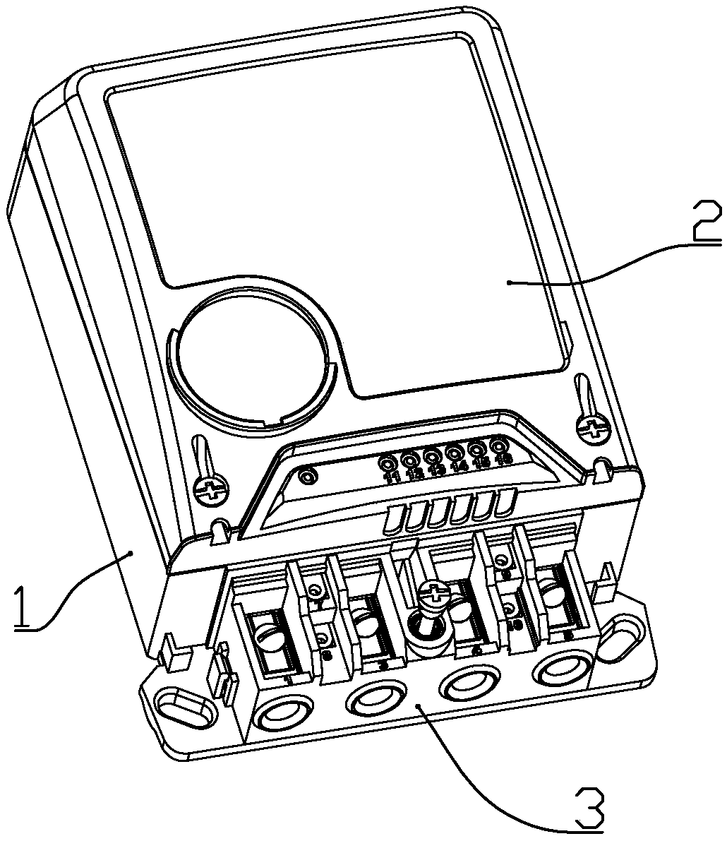
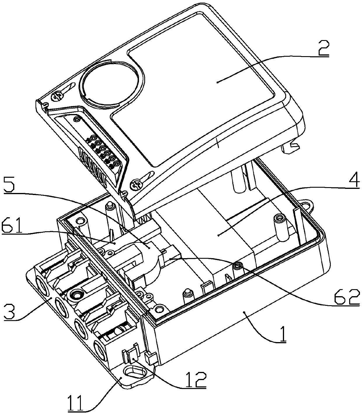
[0053] according to Figure 1 to Figure 14 As shown, an electric energy meter described in this embodiment includes a lower case 1, an upper case 2 connected to the lower case 1, a terminal block 3, and a relay 4 and a transformer 5 installed in the lower case;

[0054] A seat plate 11 is formed at the lower end of the lower housing; the terminal block 3 is mounted on the seat plate 11; the seat plate is fixedly connected with buckles 12 at both sides of the terminal block.

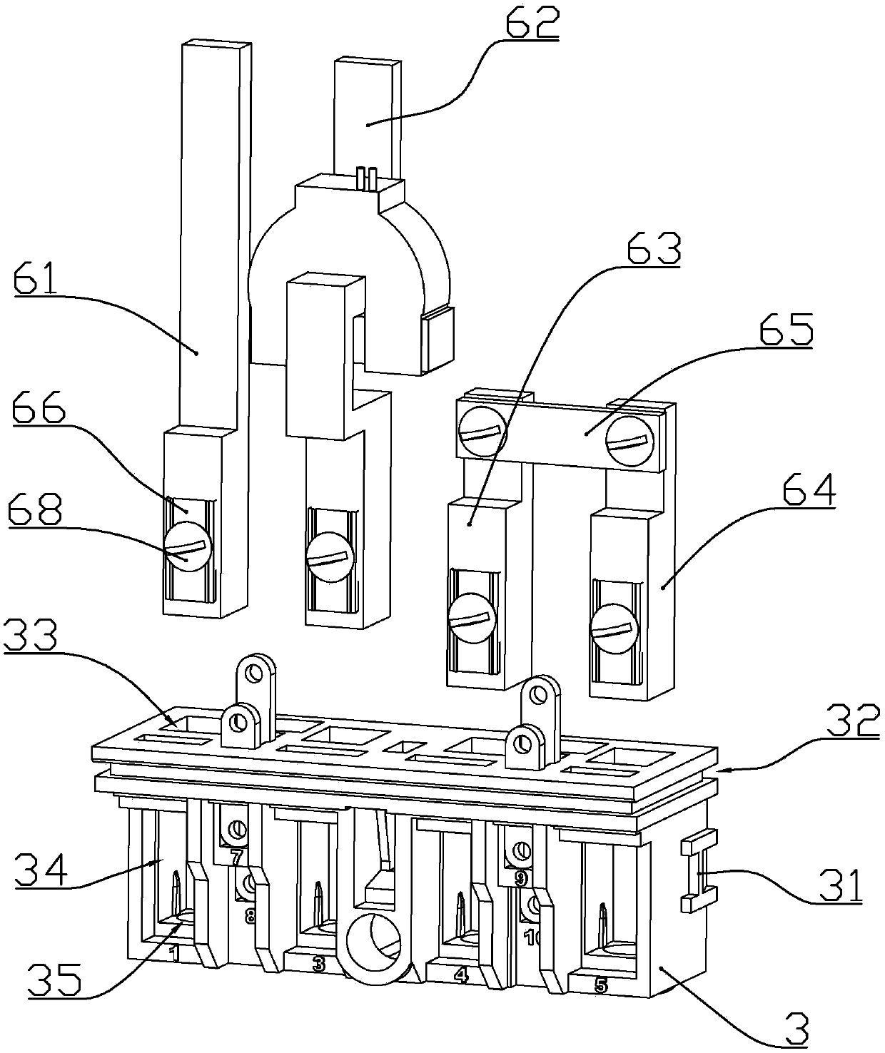
[0055] The sidewalls on both sides of the terminal block 3 are fixedly connected with clips 31 that are fixed with the clips; the terminal block is fixedly connected to the seat plate 11 through the clips 12 and the clips 31, which reduces the difficulty of installation.

[0056] The upper part of each side wall of the terminal block 3 is formed with a card slot 32;...

Embodiment 2

[0081] combine Figure 15Compared with Embodiment 1, this embodiment also makes the following improvements: the locking screw 68 connected to the first incoming line terminal, the first outgoing line terminal, the second incoming line terminal, and the second outgoing line terminal is axially formed There are internally threaded holes, and the internally threaded holes are connected with internal screws 681 .

[0082] After the wire is inserted into the conductive ferrule in the wire slot, first tighten the locking screw 68, clamp the push plate so that the conductive ferrule compresses and clamps the wire, and then tighten the inner screw so that the front end of the inner screw contacts the outer wall of the wire tight.

[0083] Compared with Embodiment 1, the locking screw of this embodiment is shorter, that is, the front end of the locking screw does not directly touch the outer wall of the wire, but the inner screw is pressed against the outer wall of the wire to fix the...

Embodiment 3

[0087] combine Figure 16 and Figure 17 , this embodiment makes the following improvements on the basis of Embodiment 1 or 2: the inner connection end of the second incoming line terminal, the second outgoing line terminal and the connection piece are connected by a locking screw 68, and the locking screw 68 An internally threaded hole is formed along the axial direction, and the internally threaded hole is a tapered hole with a wide front and a narrow rear. The thread in the internally threaded hole is a left-handed thread, and the thread on the outer wall of the locking screw is a right-handed thread; the locking screw There are 4 strip-shaped gaps equidistant along the circumference, and the strip-shaped gaps extend from the bottom of the nut of the locking screw to the front end of the locking screw; the internal thread of the internal thread hole is connected with a tapered screw with a wide front and a narrow rear. 682, the outer wall of the tapered screw is correspond...


PUM


Abstract

The invention discloses an electric energy meter, which comprises a lower housing, an upper housing connected on the lower housing, a wiring base, a relay and a transformer, wherein the relay and the transformer are arranged in the lower housing. Four terminal ports are inserted by a first incoming terminal, a first outgoing terminal, a second incoming terminal and a second outgoing terminal from the left to right in sequence. The first incoming terminal and the first outgoing terminal are connected with the relay; the first incoming terminal comprises an internal connection end and an external connection end formed at the lower end of the internal connection end; a wire slot is formed in the lower end of the external connection end; and the wire slot is internally connected with a conductive sleeve loop. The transformer is a detachable transformer, the first outgoing terminal is allowed to be connected with the relay directly, and no unnecessary connection nodes are provided, thereby reducing resistance of the first outgoing terminal part, reducing heating value and prolonging the service life of the electric energy meter.

Description

technical field [0001] The invention belongs to the technical field of electric power, in particular to an electric energy meter. Background technique [0002] The Chinese Utility Model Patent No. 201320236205.0 proposes a smart meter with an electromagnetic current transformer with antimagnetic structure; the smart meter includes a meter base, a relay, an electromagnetic current transformer, terminal blocks and a primary current transformer. conductor; the electromagnetic current transformer has an annular iron core; the above-mentioned smart meter adopts the axis of the annular iron core of the electromagnetic current transformer to be set perpendicular to the bottom plane of the electric meter base, so that the first iron core of the transformer, the second The magnetic field generated by the second iron core during one pass is perpendicular to the magnetic field generated by the magnet at the bottom of the electric energy meter, and the magnetic field generated by the ma...

Claims


Application Information

Patent Timeline
Patent Type & Authority Patents(China)
IPC IPC(8): G01R11/00G01R11/02
CPCG01R11/00G01R11/02
Inventor 王月园罗文平樊松明
Owner SHENZHEN YINJUN TECH
Why Eureka
Try Eureka