Supercharge Your Innovation With Domain-Expert AI Agents!

RCS reduction device of target support bar for RCS measurement

A support rod and target technology, applied in the direction of radio wave measurement systems, instruments, etc., can solve the problems of wave-absorbing material deformation, large measurement influence, large support rod, etc., and achieve the effect of reducing scattering

Active Publication Date: 2017-02-01
BEIHANG UNIV
View PDF3 Cites 2 Cited by
  • Summary
  • Abstract
  • Description
  • Claims
  • Application Information

AI Technical Summary

Problems solved by technology

However, the actual measurement found that the RCS of the support rod is large, and there are multiple echo reflections between the two support rods and multiple echo reflections between the support rod and the target, which has a great impact on the RCS measurement of the target to be measured
A commonly used method to solve this problem is to attach absorbing material to the outer surface of the support rod. Although the RCS of the support rod can be reduced, the attached absorbing material will rotate with the rotation of the support rod around the turntable. The direction of the relative to the incoming wave direction is always changing, and the attached absorbing material will deform with the force deformation of the support rod
The change and deformation of the direction of the absorbing material will affect the reflection path and size of the incoming wave, which will bring great difficulties to the filtering and cancellation of the support rod RCS in the post-processing process

Method used


Image

  • RCS reduction device of target support bar for RCS measurement
  • RCS reduction device of target support bar for RCS measurement
  • RCS reduction device of target support bar for RCS measurement

Examples


Embodiment Construction

[0026] The technical scheme of the present invention will be further described below in conjunction with the drawings.

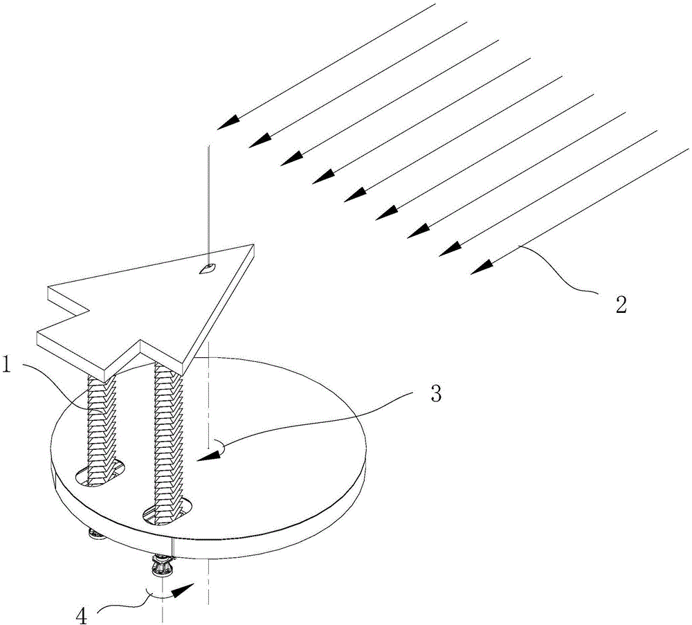
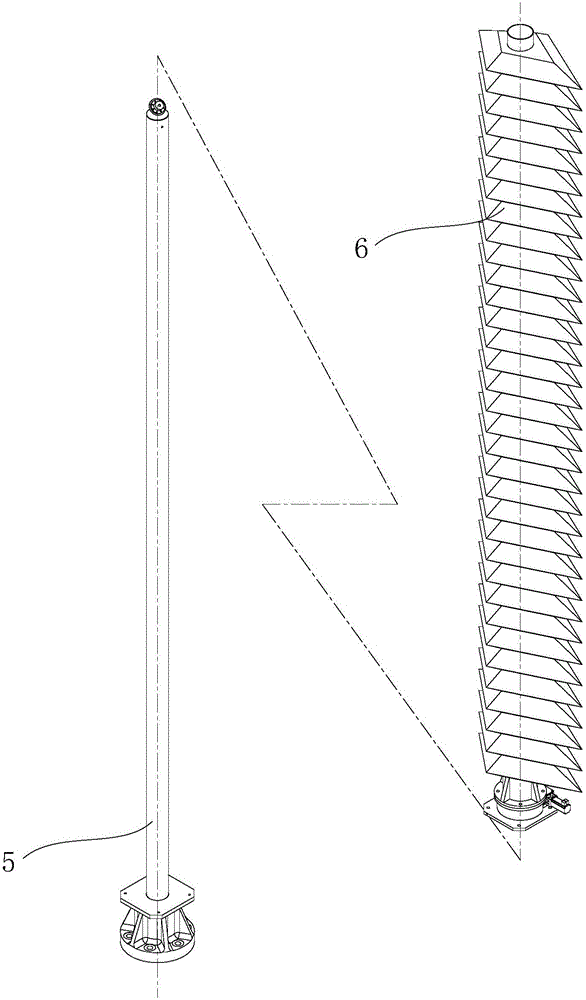
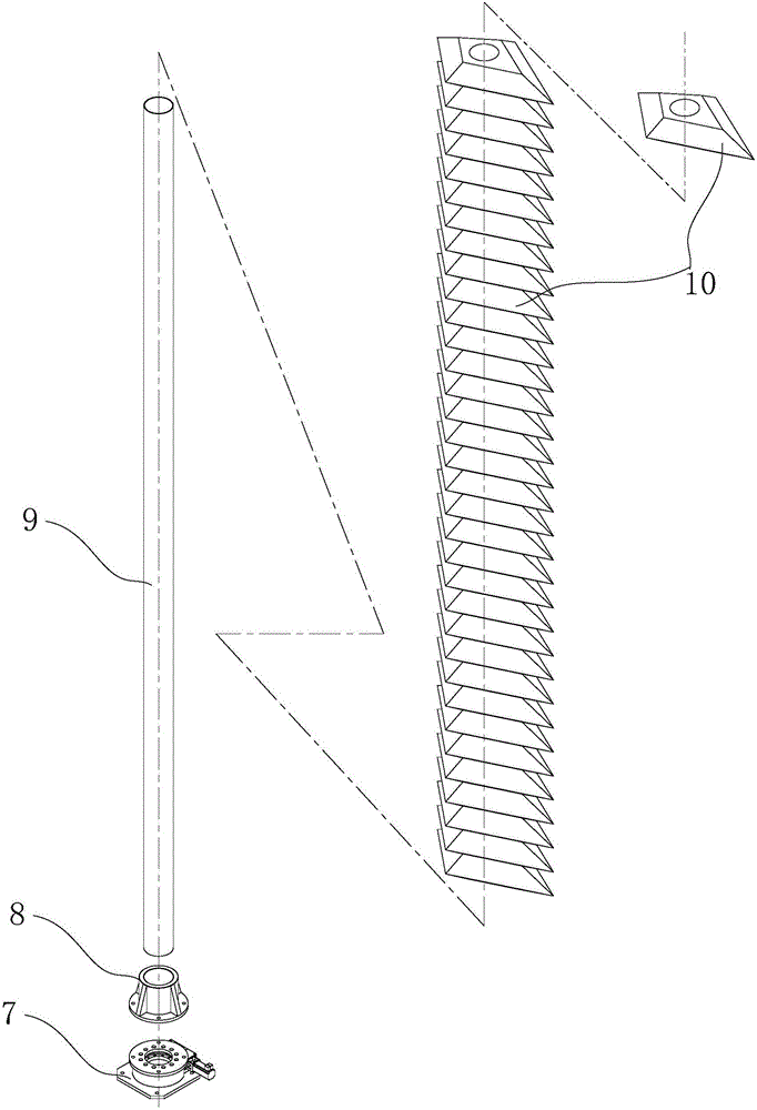
[0027] The invention provides an RCS reduction method for a target support rod for RCS measurement. Specifically, an RCS reduction device with electromagnetic wave absorption and self-rotation functions is installed on the outside of the support rod to greatly reduce the scattering of electromagnetic waves by the support rod. During the RCS measurement, the rotation speed of the target turntable is calculated, and the reverse rotation speed of the absorbing material sleeve of the RCS reduction device is calculated. The control system of the RCS reduction device is used to make the rotation direction 4 of the RCS reduction device during RCS measurement and the rotation direction of the RCS measurement turntable The direction of rotation 3 is opposite, always keep the absorbing material and wedge direction 1 relative to the direction of incoming wave 2 during RCS ...


PUM


Abstract

The present invention provides a RCS (Radar Cross Section) reduction device of a target support bar for RCS measurement. The device comprises a hollow revolution speed reducer, a flange, a PVC-U pipe and absorbing materials; the RCS reduction device with electromagnetic wave absorption and self rotation functions is installed at the external portion of the support bar to reduce the scattering of the support bar for the electromagnetic wave; according to the rotation speed of a target rotary table in the RCS measurement process, the reverse direction rotation speed of the wave-absorbing material sleeve on the RCS reduction device is calculated to allow the RCS reduction device to make reversed spinning motion according to the rotation of the support bar around the rotary table and remain the wedge direction of the wave-absorbing materials on the RCS reduction device relative to the wave incoming direction of the electromagnetic wave unchanged all the time; and the RCS reduction device is not contacted with the support bar, and the force deformation of the support bar cannot cause the deformation of the wave-absorbing materials on the RSC reduction device. In the whole RCS measurement process, the RCS reduction device remains the scattering direction and the size of the electromagnetic wave unchanged so as to reduce the difficulty.

Description

Technical field [0001] The present invention relates to an RCS reduction device for a target support rod used for RCS measurement. When an indoor test site such as a compact field is used to measure the radar cross section (hereinafter referred to as "RCS") of a stealth target, the RCS of the target support rod is mainly realized Reducing and reducing its interference to the target's own RCS measurement belongs to the fields of mechanical engineering and microwave engineering. Background technique [0002] When measuring the radar cross section (hereinafter referred to as "RCS") of stealth targets using test sites such as compact field and outdoor far field, it is necessary to use a support device to erect the target to be tested to the center of the quiet zone. The support device is generally a relatively complex machine. Structure, the scattering of electromagnetic waves is large, and even multiple echo scattering will occur, which will cause great interference in the RCS measu...

Claims


Application Information

Patent Timeline
IPC IPC(8): G01S7/02
CPCG01S7/02
Inventor 李东升王明明何国瑜陈五一
Owner BEIHANG UNIV
Features
  • R&D
  • Intellectual Property
  • Life Sciences
  • Materials
  • Tech Scout
  • Unparalleled Data Quality
  • Higher Quality Content
  • 60% Fewer Hallucinations
Learn More