Cavity type structured nano imprinting template and imprinting forming method therefor

一种纳米压印、模板的技术,应用在纳米技术、图纹面的照相制版工艺、光学等方向,能够解决很难、压力上升、压印结构缺陷等问题,达到保证脱模质量、消除溶解/吸附的的效果

Active Publication Date: 2017-02-01
SHANDONG UNIV OF SCI & TECH
View PDF6 Cites 3 Cited by
  • Summary
  • Abstract
  • Description
  • Claims
  • Application Information

AI Technical Summary

Problems solved by technology

However, this demoulding structure / method is difficult or even impossible to apply to the imprinting molding conditions of a large-area high-aspect-ratio imprinting structure
The reason is that for the imprint molding of a large-area high-aspect-ratio imprint structure, due to the large interface area between the imprint glue and the template, the permeation speed of gas molecules is slow, and the demoulding efficiency is low. There is still a greater risk of the structure being pulled out
[0013] It is especially important that, on the one hand, since the template groove (or "hole") is an impermeable structure, there must be residual air inside. During the imprinting process, especially for large areas Compared with the embossing process of the embossed structure, on the one hand, the required pressure will increase significantly, and, under higher pressure, the above-mentioned "residual air" will enter the interior of the embossed rubber to form bubbles / cavities, resulting in The internal defects of the embossed structure reduce the imprint quality; on the other hand, during the demoulding process, the force on the embossed sample is mainly in the form of upward "pull force" (the upward "pull force" exerted by the air film "Only seven auxiliary functions)
In this way, the raised middle part of the embossed structure, under the action of upward pulling force, inevitably still has a "neck phenomenon", which in turn causes the problem that the embossed structure is pulled off

Method used


Image

  • Cavity type structured nano imprinting template and imprinting forming method therefor
  • Cavity type structured nano imprinting template and imprinting forming method therefor
  • Cavity type structured nano imprinting template and imprinting forming method therefor

Examples


Embodiment 1

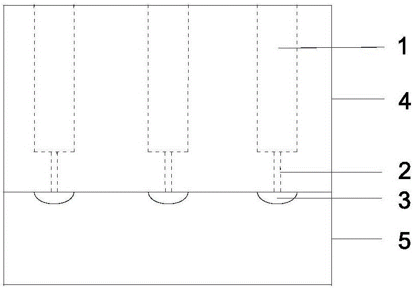
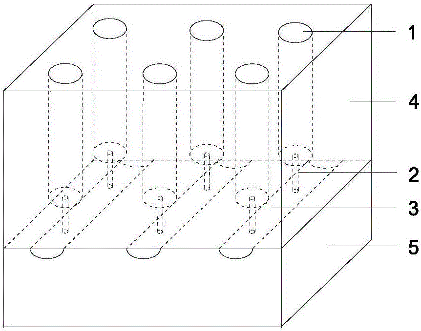
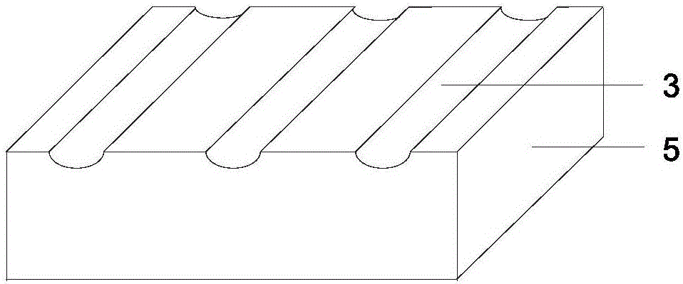
[0057] Such as Figures 1 to 3 As shown, the cavity structure nanoimprint template of the present invention has an integrated structure, including two parts of an upper template 4 and a lower template 5 welded together;

[0058] The upper template is evenly provided with a certain number of stepped holes, the above-mentioned stepped holes are thick at the top and thin at the bottom, and run through the upper and lower surfaces of the upper template; the upper part 1 of the stepped hole has a diameter of 10 microns and a hole depth of 100 microns. The diameter of the lower part 2 is 100nm;

[0059] The number of the above-mentioned stepped holes and the relative positions between the stepped holes correspond to the number of structural protrusions required to be embossed and the relative positions between the structural protrusions; the dimensions of the upper parts of the stepped holes are respectively One-to-one corresponding to the size of the structural protrusions to be e...


PUM


Abstract

The invention discloses a cavity type structured nano imprinting template and an imprinting forming method therefor. The cavity type structured nano imprinting template adopts an integrated structure, and comprises an upper template and a lower template which are welded together, wherein multiple thorough stepped holes are uniformly formed in the upper template; multiple trenches are uniformly formed in the lower template; and the two ends of the trenches are connected with an external high-pressure water pump and a vacuum pump through pipelines. According to the cavity type structured nano imprinting template, a sealed hollow cavity is additionally formed in the template, so that negative pressure is formed by vacuumizing the cavity of the template in the imprinting process; and in a demolding process, cracks are generated on the interface of the template and imprinting adhesive through water pressure, and then the cracks extend to the overall combination interface to complete the demolding. Compared with the prior art, the cavity type structured nano imprinting template has the beneficial effects of simple and convenient operation, low required pressure for imprinting, good forming quality and the like, so that the cavity type structured nano imprinting template is suitable for forming a normal imprinting structure and particularly suitable for forming an imprinting structure with high aspect ratio.

Description

technical field [0001] The invention relates to a nano-imprint template and an imprint forming method thereof, in particular to a cavity-structured nano-imprint template and an imprint forming method thereof, belonging to the technical field of micro-nano device production. Background technique [0002] Nanoimprinting includes the imprinting process and the demoulding process, both of which are equally important for the quality of the imprint. [0003] For nanoimprinting with a lower aspect ratio, the quality of the product mainly depends on the release effect of nanoimprinting, and the quality of the imprinting process is usually easy to guarantee or achieve. The degree of impact on the quality of the final product is relatively small. [0004] However, as the embossing structure changes from high aspect ratios to higher aspect ratios, the impact of the embossing process on the quality of the final product will increase rapidly until it is as important as the demoulding pr...

Claims


Application Information

Patent Timeline
Patent Type & Authority Applications(China)
IPC IPC(8): G03F7/00B82Y40/00
CPCB82Y40/00G03F7/0002B29C2059/023B29C59/026
Inventor 王清张金涛张睿郑旭马立俊张星远杜文全
Owner SHANDONG UNIV OF SCI & TECH
Why Eureka
Try Eureka