
Collector porcelain cylinder on multi-stage depressurization collector and collector including the same

A collector and cylinder technology, applied in the field of collectors, can solve the problems of increasing the assembly space of the inner collector, limiting the miniaturization of the collector, and cumbersome assembling process of the ceramic cylinder, so as to avoid the superposition effect, improve the efficiency, and be easy to locate. Effect

Active Publication Date: 2018-10-30
北京真空电子技术研究所
View PDF4 Cites 0 Cited by
  • Summary
  • Abstract
  • Description
  • Claims
  • Application Information

AI Technical Summary

Problems solved by technology

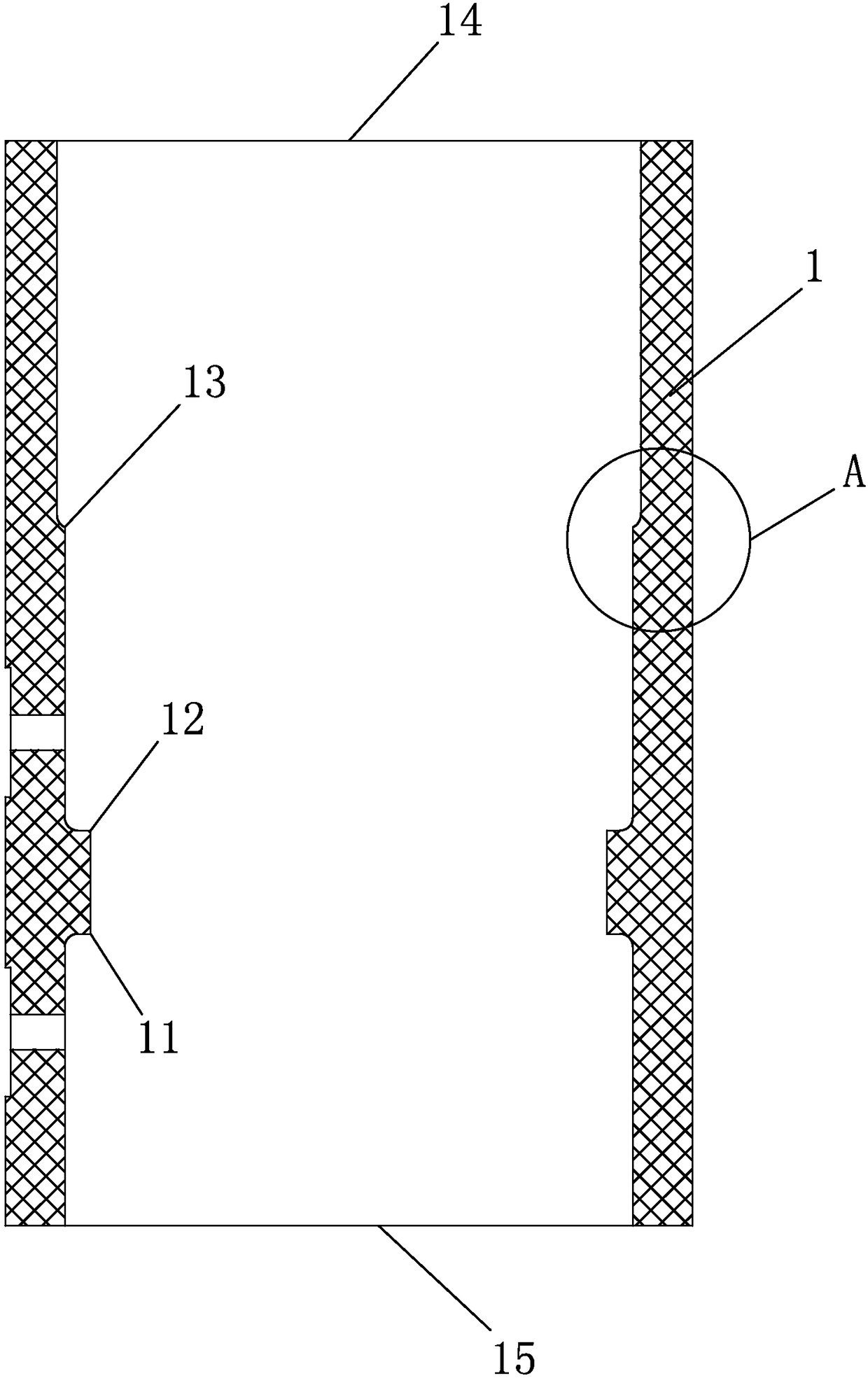
[0005] The first technical problem to be solved by the present invention is to provide a collector porcelain cylinder on a multi-stage depressurization collector; the collector porcelain cylinder body provided by the present invention is a cylindrical integrated structure, which solves the problem of traditional multi-lobe The assembly process of structural porcelain cylinder or split structure porcelain cylinder is cumbersome, and the porcelain cylinder is easy to deform during the assembly process, which greatly reduces the tolerance of the porcelain cylinder and the inner collector during the assembly process, and avoids the assembly of various parts The superposition effect produced between tolerances; for high-voltage traveling wave tubes, the ceramic cylinder with split structure obviously limits the miniaturization of the collector. The electrical distance needs to increase the thickness of the ceramic petals. The integral porcelain cylinder provided by the present invention maximizes the assembly space of the inner collector, so the inner collector can be made as large as possible, and at the same time, it can be conveniently designed to collect The insulation distance between the poles improves the efficiency of the collector and the withstand voltage strength, which facilitates the miniaturization of the collector

Method used


Image

  • Collector porcelain cylinder on multi-stage depressurization collector and collector including the same
  • Collector porcelain cylinder on multi-stage depressurization collector and collector including the same
  • Collector porcelain cylinder on multi-stage depressurization collector and collector including the same

Examples


Embodiment 1

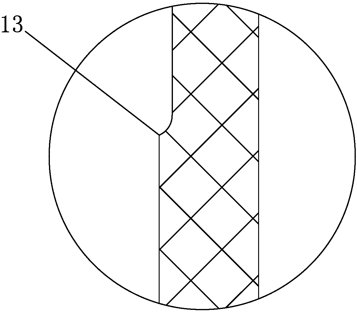
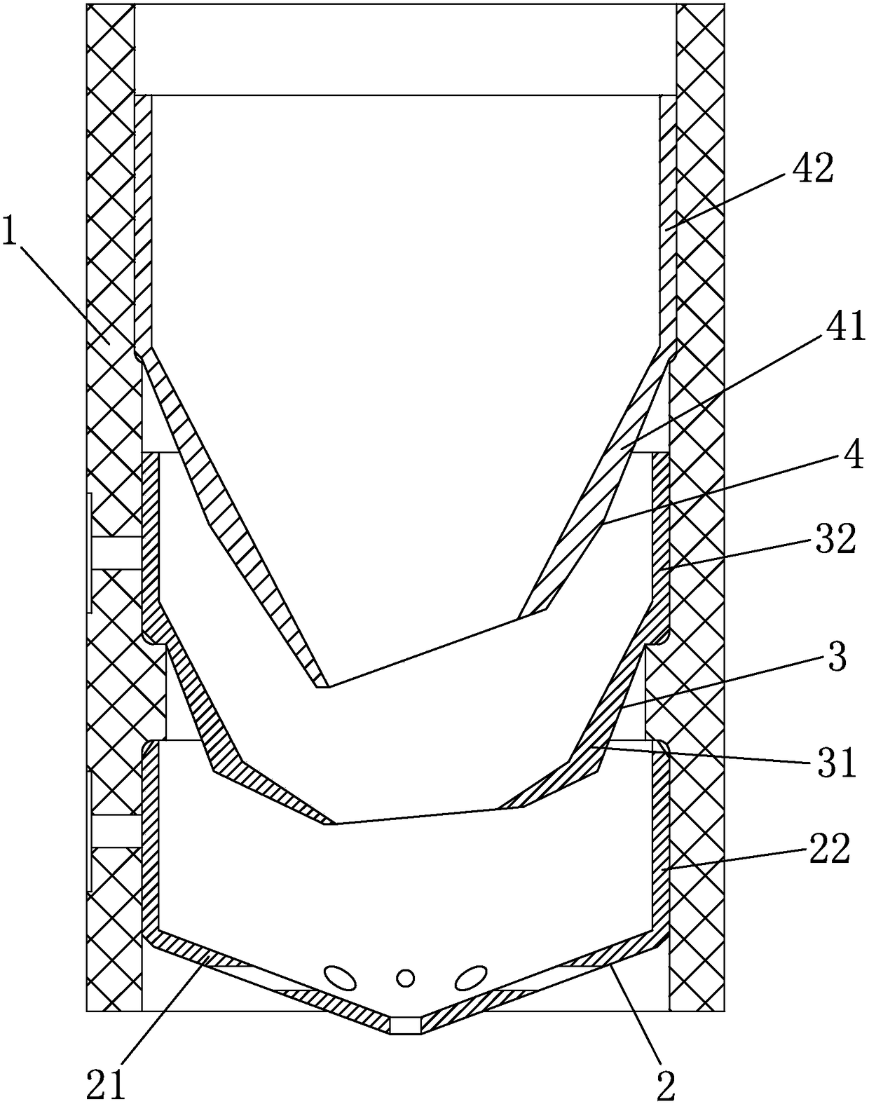
[0053] Such as figure 1 , 2 As shown in , 3, a collector porcelain cylinder on a multi-stage decompression collector, in this embodiment, the collector porcelain cylinder 1 is a cylinder body with a three-stage depressurization function, and the collector pole porcelain cylinder 1 The cylinder body is a cylindrical integrated structure; the cylinder inner wall of the collector porcelain cylinder 1 is provided with a limit boss for positioning and installing the inner collector set in the collector porcelain cylinder;

[0054] The limiting boss includes a first limiting platform 11 for positioning and installing the first inner collector 2, a second limiting platform 12 for positioning and installing the second inner collector 3, and a second limiting platform for positioning and installing. The third limiting platform 13 of the third inner collector 4 .

[0055] The setting direction of the second limiting platform 12 is the same as that of the third limiting platform 13, bo...

Embodiment 2

[0061] Such as Figure 4 , 5 As shown, a collector porcelain cylinder on a multi-stage decompression collector. In this embodiment, the collector porcelain cylinder 1 is a cylinder body with a three-stage depressurization function, and the cylinder of the collector pole ceramic cylinder 1 The body is a cylindrical integrated structure; the inner wall of the collector porcelain cylinder 1 is provided with a limit boss for positioning and installing the inner collector set in the collector porcelain cylinder;

[0062] The limiting boss includes a first limiting platform 11 for positioning and installing the first inner collector 2, a second limiting platform 12 for positioning and installing the second inner collector 3, and a second limiting platform for positioning and installing. The third limiting platform 13 of the third inner collector 4 .

[0063] The setting direction of the first limiting platform 11, the setting direction of the second limiting platform 12 and the se...

Embodiment 3

[0070] Such as Image 6 , 7 As shown, a collector porcelain cylinder on a multi-stage decompression collector. In this embodiment, the collector porcelain cylinder 1 is a cylinder body with a three-stage depressurization function, and the cylinder of the collector pole ceramic cylinder 1 The body is a cylindrical integrated structure; the inner wall of the collector porcelain cylinder 1 is provided with a limit boss for positioning and installing the inner collector set in the collector porcelain cylinder;

[0071] The limiting boss includes a first limiting platform 11 for positioning and installing the first inner collector 2, a second limiting platform 12 for positioning and installing the second inner collector 3, and a second limiting platform for positioning and installing. The third limiting platform 13 of the third inner collector 4 .

[0072]The setting direction of the first limiting platform 11, the setting direction of the second limiting platform 12 and the sett...


PUM


Abstract

The invention discloses a collector porcelain cylinder on a multi-stage depressed collector and a collector comprising the porcelain cylinder. The collector porcelain cylinder comprises a cylinder body with at least three-stage depression function, wherein the cylinder body of the collector porcelain cylinder is in a cylindrical integral structure; and a limiting boss used for positioning and mounting inner collectors arranged in the collector porcelain cylinder is arranged on an inner wall of the cylinder body of the collector porcelain cylinder. The collector porcelain cylinder solves the problems that the traditional porcelain cylinder in a multi-section or split structure is complicated in assembling procedure and easily deforms in an assembling process. According to the collector comprising the porcelain cylinder, compared with the traditional collector, the assembling process is simple; positioning and assembling of the inner collectors are easy to realize; and the superposition error generated by the collector during assembling is small.

Description

technical field [0001] The invention belongs to the field of vacuum microwave electronic devices, and in particular relates to a collector porcelain cylinder on a multi-stage decompression collector and a collector including the porcelain cylinder. Background technique [0002] Traveling wave tubes are currently the most widely used electric vacuum devices. Millimeter-wave traveling-wave tubes are mainly used in communications, radar, missile-borne seekers, electronic countermeasures, and other fields; due to strict restrictions on volume and weight in airborne, aerospace applications, and synthetic applications, millimeter-wave traveling-wave tubes face With the requirement of miniaturization. [0003] The collector is the part in the traveling wave tube that receives the electron beam and recovers the energy. At present, most millimeter-wave broadband high-power traveling wave tubes use multi-stage step-down collectors, which recover energy from the electron beam, thereb...

Claims


Application Information

Patent Timeline
Patent Type & Authority Patents(China)
IPC IPC(8): H01J23/027H01J25/34H01J9/02H01J9/14H01J9/18
CPCH01J9/02H01J9/14H01J9/18H01J23/0275H01J25/34
Inventor 常田颖杨小萌李伟李紫琳
Owner 北京真空电子技术研究所
Learn More