Charging circuit, electronic equipment and charging method

A technology of charging circuit and electronic equipment, which is applied in the field of communication, can solve the problems of triode with low charging efficiency, heat loss of power loss triode, and reduce the performance of triode, so as to achieve the effect of improving charging efficiency, reducing power loss and improving performance

Inactive Publication Date: 2017-02-01
SHENZHEN TINNO WIRELESS TECH
View PDF7 Cites 2 Cited by
  • Summary
  • Abstract
  • Description
  • Claims
  • Application Information

AI Technical Summary

Problems solved by technology

[0009] In view of this, embodiments of the present invention provide a charging circuit, electronic equipment and a charging method, which are used to solve the problem of low battery charging efficiency of electronic equipment in the prior art and the power loss of the triode, which causes the triode to heat up and reduces the performance of the triode. The problem

Method used


Image

  • Charging circuit, electronic equipment and charging method
  • Charging circuit, electronic equipment and charging method
  • Charging circuit, electronic equipment and charging method

Examples


Embodiment 1

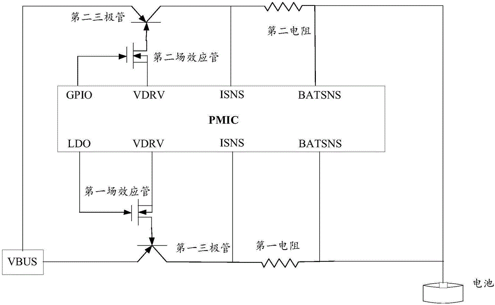
[0048] The embodiment of the present invention provides a charging circuit, which includes: a power management chip (PowerManagement Integrated Circuits, PMIC), a main charging circuit, and at least one slave charging circuit, see figure 1 , Which is a circuit diagram of a charging circuit provided by an embodiment of the present invention. In the charging circuit, a slave charging circuit is used as an example. In practical applications, it is not limited to only one slave charging circuit.

[0049] Such as figure 1 As shown, the main charging circuit includes a first triode, a first field effect tube, and a first resistor, wherein the emitter of the first triode is connected to the output terminal of the charger, and the The collectors are respectively connected to the PMIC and one end of the first resistor, the base of the first triode is connected to the source of the first field effect tube, the drain of the first field effect tube is connected to the PMIC, the first field Th...

Embodiment 2

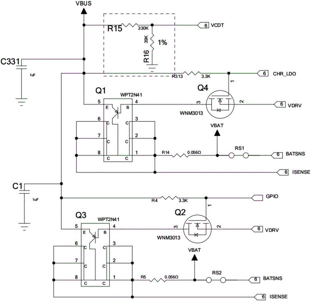
[0064] figure 2 This is a circuit diagram of a specific charging circuit provided by an embodiment of the present invention. The circuit diagram is specifically a charging circuit diagram for charging a battery of a mobile phone provided by an embodiment of the present invention. In this embodiment, the charging circuit includes a slave charging circuit. As an example, the charging circuit also includes a resistor R15 with one end grounded and one end connected to the VCDT port of the PMIC, with a resistance value of 330KΩ, one end connected to the VCDT port, one end connected to the charger VBUS resistor R16, and one end connected to VBUS. , The capacitor C331 with one end grounded has a capacitance of 1μF, one end is connected to the main circuit, and the other end is grounded capacitor C1, with a capacitance of 1uF.

[0065] The main charging circuit includes:

[0066] The first transistor Q1, its model is WPT2N41.

[0067] The first field effect tube Q4, its model is WNM3013.

...

Embodiment 3

[0085] An embodiment of the present invention also provides an electronic device including the charging circuit as described in the first embodiment.

[0086] In the embodiment of the present invention, the main charging circuit and the slave charging circuit are used to jointly charge the battery, so that the common power loss of the first triode in the main charging circuit and the second triode in the slave charging circuit is lower than the existing The power loss of the triode in the charging circuit in the technology improves the charging efficiency of the battery of the electronic device, and also reduces the degree of heat caused by the power loss of the first triode and the second triode, and improves the first The performance of the triode and the second triode.


PUM


Abstract

The invention provides a charging circuit, electronic equipment and a charging method. The charging circuit comprises a power management chip PMIC, a main charging circuit and at least one slave charging circuit. In the embodiment of the invention, the total power loss of a first triode in the main charging circuit and a second triode in the slave charging circuit is lower than the power loss of a triode in the charging circuit in the prior art by using the main charging circuit and the slave charging circuit to jointly charge a battery, so that the charging efficiency of the battery of the electronic equipment is improved; and moreover, the heat generation degree caused by the power loss of the first triode and the second triode is reduced, and the application performance of the first triode and the second triode is improved.

Description

Technical field [0001] The present invention relates to the field of communication technology, in particular to a charging circuit, electronic equipment and a charging method. Background technique [0002] With the development of science and technology, electronic devices are becoming more and more popular. When charging the batteries of electronic devices, the charging process includes three stages: [0003] Pre-charge (Pre-charge) process, constant-current charge (Constant-Current, CC) process, and constant-voltage charge (Constant-Voltage, CV) process. [0004] In the prior art, the amplification characteristics of the bipolar junction transistor (BJT) in the linear region can be used to charge the battery of the electronic device. Among them, the bipolar junction transistor can also be referred to as a semiconductor transistor and a transistor. Hereinafter referred to as triode. [0005] During the charging process, the power management chip inside the electronic device dynamical...

Claims


Application Information

Patent Timeline
Patent Type & Authority Applications(China)
IPC IPC(8): H02J7/00H01M10/44
CPCH01M10/44H02J7/00Y02B40/00Y02E60/10
Inventor 何震宇刘文戴大为
Owner SHENZHEN TINNO WIRELESS TECH
Why Eureka
Try Eureka