Rotary permanent-magnet suction scheme capable of switching on/off shielding in groove

An internal rotation, magnetic technology, applied in the direction of electrical components, generators/motors, etc., can solve the problems of incomplete demagnetization, large demagnetization conversion resistance and high cost

Active Publication Date: 2017-02-01
王汉城 +1
View PDF5 Cites 3 Cited by
  • Summary
  • Abstract
  • Description
  • Claims
  • Application Information

AI Technical Summary

Problems solved by technology

[0003] The technical problem to be solved by the present invention is to provide a kind of magnetization and degaussing conversion resistance for the above-mentioned prior art: heavy self-weight, high cost, wide magnetic poles, too many processes, or incomplete degaussing, or high magnetization and degaussing conversion resistance. Let the permanent magnet move or rotate in a certain way in the pole slot to achieve the working state of magnetization or demagnetization; it has low cost, less process, light weight, demagnetization, high magnetic field density, small conversion force, and convenient operation. It can be made into various large or small permanent magnet magnetic equipment; although the current magnetic attraction has appeared to use the method of rotating in the slot to achieve demagnetization and magnetization, but that is done in the same layer of magnetic poles, and its magnetic poles need Separate it into many segments with a magnetic partition

Method used


Image

  • Rotary permanent-magnet suction scheme capable of switching on/off shielding in groove
  • Rotary permanent-magnet suction scheme capable of switching on/off shielding in groove
  • Rotary permanent-magnet suction scheme capable of switching on/off shielding in groove

Examples


Embodiment 1

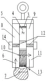
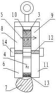
[0018] Embodiment 1: as figure 1 , 2 As shown, the lower working pole 6 and the upper working pole 8 are separated by a magnetic separator 12, and the upper working magnetic pole 9 and the lower working magnetic pole 11 are also separated by a magnetic separator 12, and a cylinder 3 is arranged in the middle of them, and the cylinder 3 An iron body 4 and a permanent magnet 10 are arranged, and a shaft 14 is connected among them, and a protective plate 13 is arranged on the lower part thereof. Wherein the rotatable body 1 that cylinder body 3, iron body 4 and permanent magnet 10 are formed can rotate with shaft 14, when rotating to figure 1 When it is in the magnetic state, when it is rotated to figure 2 It is in the degaussed state.

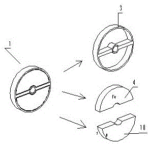
[0019] another example image 3 Shown is an exploded view of the rotatable body 1 . Wherein the cylindrical body 3 has an inner shaft sleeve and reinforcing ribs.

Embodiment 2

[0020] Embodiment 2: as Figure 4 As shown, stacking several examples 1 can also become a magnetic pick-and-release solution.

Embodiment 3

[0021] Embodiment 3: as Figure 5 As shown, in Example 1, several rotating bodies and shafts are stacked in the direction shown, which can become another magnetic suction and release scheme.


PUM


Abstract

The invention discloses a novel method of permanent magnet equipment. Aiming at the states of heavy weight, high cost, wide magnetic pole and high conversion force for magnetization and demagnetization occurring in application of an existing permanent-magnet material in a lift device, a planar suction plate and a welding positioning technology, a method for achieving magnetization and demagnetization by also using a rotation or translation mode to achieve open-close circulation of a magnetic field without digging holes in an inner magnetic pole and an outer magnetic pole is provided. The permanent-magnet material has the advantages of lower cost, lighter weight, large magnetic field density and smaller conversion force, and can be conveniently fabricated to various large-size or small-size light magnetic equipment.

Description

technical field [0001] The invention belongs to the field of machinery, and in particular relates to a permanent magnetic device, a suction hoist used for conveying steel, a plane suction plate of a machine tool, and a welding clamping device. Background technique [0002] At present, the magnetization or degaussing methods of permanent magnet magnetic equipment with pure mechanical movement can be roughly divided into three categories. One is to use the rotation of the magnetic pole to short-circuit the magnetic field; the other is to move the permanent magnet horizontally so that the horizontal permanent magnet and the vertical permanent magnet are in the same direction or The third is the method of forcibly disconnecting or connecting the magnetic circuit; the products of these three methods have been widely used, and each has its own advantages and disadvantages; for example, the first type has manual and automatic cycle permanent magnet cranes. Rotation method, so it ne...

Claims


Application Information

Patent Timeline
Patent Type & Authority Applications(China)
IPC IPC(8): H02N11/00
CPCH02N11/006
Inventor 不公告发明人
Owner 王汉城
Why Eureka
Try Eureka