Electronic device in wireless communication system and wireless communication method

A technology for wireless communication systems and electronic equipment, applied in wireless communication, radio transmission systems, diversity/multi-antenna systems, etc., can solve the problems of pilot pollution, difficult implementation, strong algorithm assumptions, etc., to achieve optimal configuration and reduced interference , the effect of improving the overall performance

Inactive Publication Date: 2017-02-01
SONY CORP
View PDF6 Cites 8 Cited by
  • Summary
  • Abstract
  • Description
  • Claims
  • Application Information

AI Technical Summary

Problems solved by technology

At this time, the pilot signals sent by users using the same or incompletely orthogonal pilot sequences in different cells will be received by the base station, but the base station cannot effectively distinguish these pilot signals, resulting in channel estimation at the base station. disturbed
When the base station uses the interfered channel estimation for uplink data detection, it will not only receive the data sent by the users in this cell, but also receive the data of users in other cells, thus causing uplink inter-cell interference
On the other hand, when the base station uses the interfered channel estimate to generate a precoding matrix and transmit downlink data, users in other cells will also receive the data in addition to the users in this cell, thus causing inter-cell interference in the downlink
[0005] Theoretical research shows that although the spectral efficiency and energy efficiency of massive MIMO systems can be significantly improved, and as the number of base station antennas increases, the impact of noise and channel estimation errors on system performance becomes smaller and smaller, but the pilot pollution caused by However, the inter-cell interference cannot be eliminated, and has become one of the performance limiting factors of massive MIMO systems
[0006] Existing methods for mitigating pilot pollution often have the following problems: 1. Algorithm assumptions are too strong, and can only be well satisfied when the number of base station antennas reaches infinite; 2. A large amount of prior information and multi-cell coordination are required Cooperation, to obtain part of the performance gain with huge overhead in other aspects; 3. The algorithm complexity is extremely high, which is often difficult to achieve in actual systems
Therefore, the existing methods to alleviate the problem of pilot pollution are often difficult to adapt to the current technical conditions, so in practical applications, pilot pollution is still one of the serious problems faced by massive MIMO systems

Method used

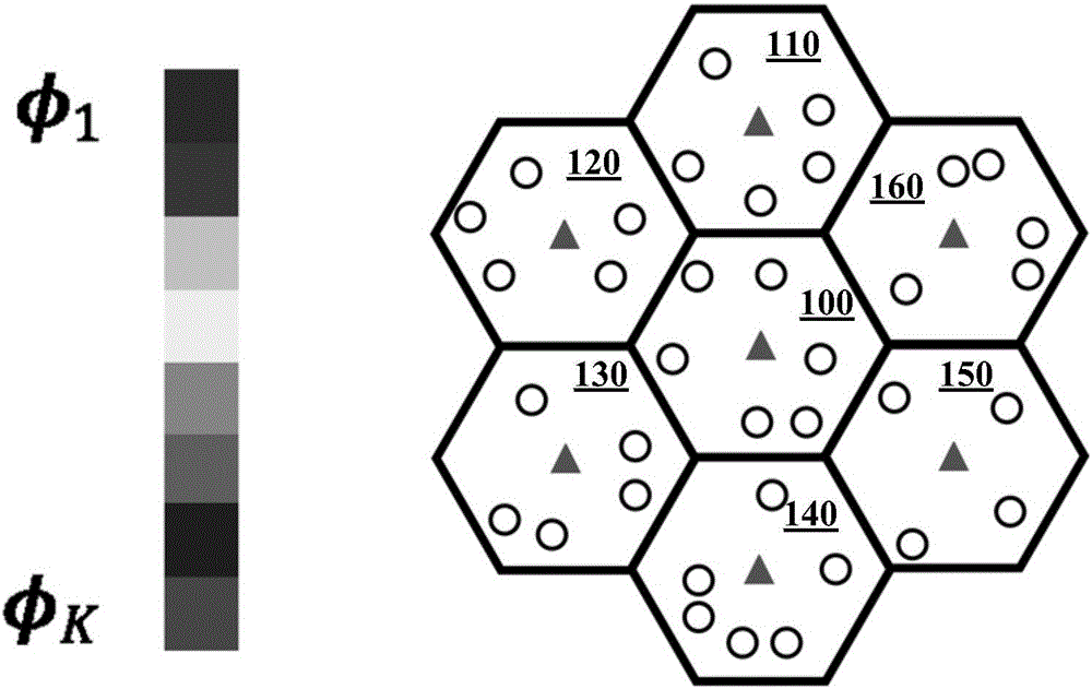
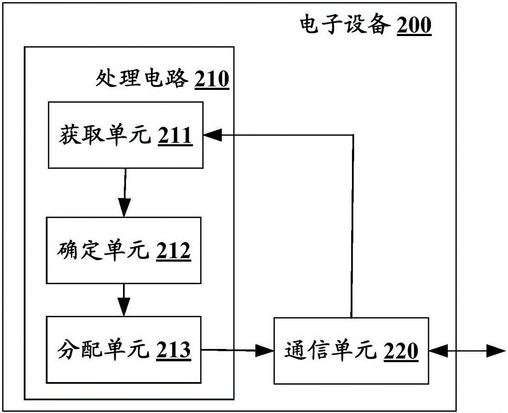

Image

  • Electronic device in wireless communication system and wireless communication method
  • Electronic device in wireless communication system and wireless communication method
  • Electronic device in wireless communication system and wireless communication method

Examples


Embodiment Construction

[0036]Examples of the present disclosure will now be described more fully with reference to the accompanying drawings. The following description is merely exemplary in nature and is not intended to limit the disclosure, application or uses.

[0037] Example embodiments are provided so that this disclosure will be thorough, and will fully convey the scope to those who are skilled in the art. Numerous specific details are set forth such as examples of specific components, devices and methods, to provide a thorough understanding of embodiments of the present disclosure. It will be apparent to those skilled in the art that specific details need not be employed, that example embodiments may be embodied in many different forms, and that neither should be construed to limit the scope of the disclosure. In some example embodiments, well-known processes, well-known structures, and well-known technologies are not described in detail.

[0038] The UE (User Equipment, user equipment) in...


PUM


Abstract

The disclosure relates to an electronic device in a wireless communication system and a wireless communication method. A plurality of cells exist in a wireless communication system and include a current cell where the electronic device is located and an adjacent cell. The electronic device consists of one or more processing circuits. The processing circuits are configured to execute the following operations: distribution information of reference signals of the current cell and the adjacent cell is obtained; on the basis of the distribution information, the quality of an available reference signal in the current cell is determined; and the available dereference signal is distributed to user equipment based on the quality of the available reference signal. With the electronic device and wireless communication method, the quality of the available reference signal can be monitored based on interaction information between base stations, thereby realizing optimized configuration of the reference signal and improving the overall performance of the system.

Description

technical field [0001] The present disclosure relates to the technical field of wireless communication, and in particular to an electronic device in a wireless communication system and a method for performing wireless communication in the wireless communication system. Background technique [0002] This section provides background information related to the present disclosure which is not necessarily prior art. [0003] Massive MIMO (Multi-input Multi-output) systems have attracted extensive attention from academia and industry in recent years. Theoretical studies have shown that by using simple linear algorithms such as zero-forcing algorithm and minimum mean square error algorithm, massive MIMO systems can significantly improve the spectral efficiency and energy efficiency of the system at the same time, so it is likely to be adopted as the key to the next generation communication standard technology. [0004] The performance of massive MIMO systems in multi-cell time-di...

Claims


Application Information

Patent Timeline
Patent Type & Authority Applications(China)
IPC IPC(8): H04B7/04H04W72/08
CPCH04B7/0413H04W72/542H04W24/10H04L5/0048H04W16/10H04L5/0023H04L5/0032H04L5/006H04L5/0091H04W72/27H04L27/261H04W36/0044H04W36/0061H04W36/0088
Inventor 竺旭东王昭诚陈晋辉
Owner SONY CORP
Why Eureka
Try Eureka