Electrolyte tubular reactor and reaction method
A tubular reactor and electrolyte technology, applied in the chemical industry, can solve the problems of high energy consumption, long time, low efficiency, etc., and achieve the effects of wide quality range, small batch and short process time
- Summary
- Abstract
- Description
- Claims
- Application Information
AI Technical Summary
Problems solved by technology
Method used
Image
Examples
specific Embodiment approach
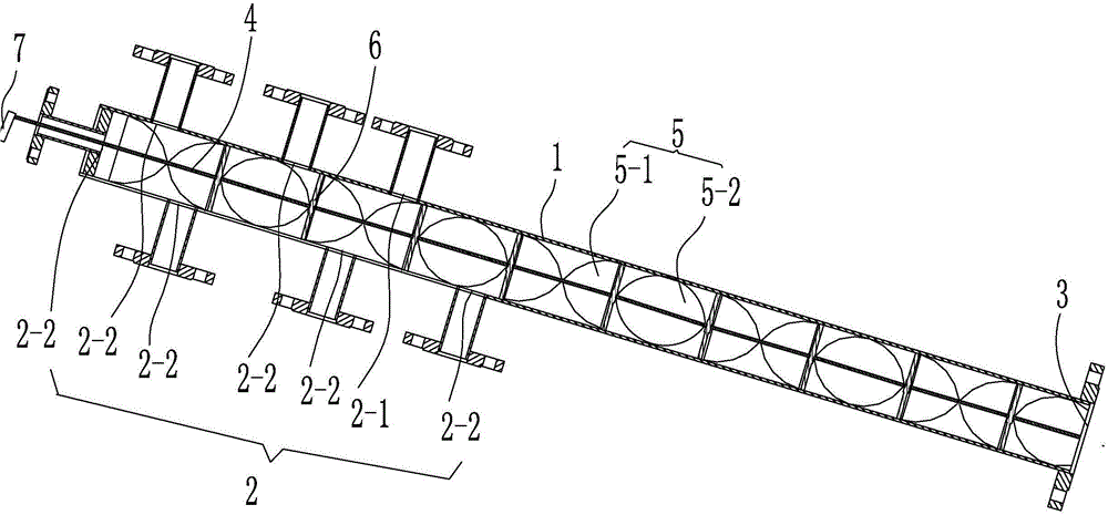
[0031] An electrolyte tubular reactor, characterized in that: it includes a reaction tube body 1 with a reaction cavity inside, the tube body of the reaction tube body 1 is arranged with one end high and one end low, and the reaction tube body 1 is at a height One end is provided with a plurality of raw material inlets 2 for adding different electrolytes to prepare raw materials, and the lower end is provided with a discharge port 3 for discharging electrolytes;
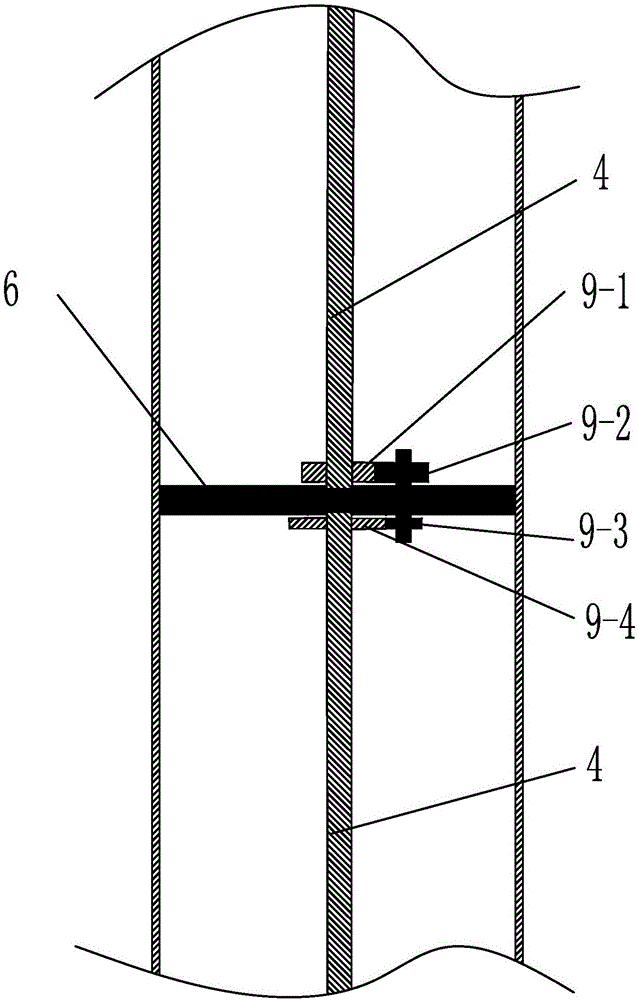
[0032] In the cavity of the reaction tube body 1, along the axial direction of the reaction tube body 1, a plurality of rotating shaft segments 4 rotating around the same axis line are sequentially arranged, and the rotational speeds and / or steering directions of two adjacent rotating shaft segments 4 are different from each other The cavity of the reaction tube body 1 is also provided with a transmission device between two adjacent rotating shaft segments 4 to make the rotational speed and / or steering of the adjacent...
Embodiment 1
[0047] Such as figure 1 As shown, an electrolyte tubular reactor is characterized in that: it includes a reaction tube body 1 with a reaction cavity inside, and the tube body of the reaction tube body 1 is arranged with one end high and one end low, and the reaction tube body 1 The high end is provided with a plurality of raw material inlets 2 for adding different electrolytes to prepare raw materials, and the low end is provided with a discharge port 3 for discharging the electrolyte;
[0048] In the cavity of the reaction tube body 1, along the axial direction of the reaction tube body 1, a plurality of rotating shaft segments 4 rotating around the same axis line are sequentially arranged, and the rotational speeds and / or steering directions of two adjacent rotating shaft segments 4 are different from each other The cavity of the reaction tube body 1 is also provided with a transmission device between two adjacent rotating shaft segments 4 to make the rotational speed and / or...
Embodiment 2
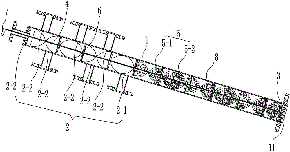
[0054] Such as figure 2 As shown, different from the above embodiment, in order to make EC not easy to freeze, at least one raw material feeding port 2 is the EC feeding port 2-1 for connecting with the EC raw material supply device, and the remaining raw material feeding ports Port 2 is other raw material feed port 2-2 for connecting with other electrolyte preparation raw material supply devices; the connection position between EC feed port 2-1 and reaction tube body 1 is located at other raw material feed port 2 After -2; and the mixing and stirring plate located after the EC feeding port 2-1 is provided with microholes 8 penetrating the mixing and stirring plate.
[0055] A filter screen 11 is provided in the discharge port 3 .
PUM
| Property | Measurement | Unit |
|---|---|---|
| diameter | aaaaa | aaaaa |
| melting point | aaaaa | aaaaa |
Abstract
Description
Claims
Application Information
 - R&D
- Intellectual Property
- Life Sciences
- Materials
- Tech Scout
- Unparalleled Data Quality
- Higher Quality Content
- 60% Fewer Hallucinations
Browse by: Latest US Patents, China's latest patents, Technical Efficacy Thesaurus, Application Domain, Technology Topic, Popular Technical Reports.
© 2025 PatSnap. All rights reserved.Legal|Privacy policy|Modern Slavery Act Transparency Statement|Sitemap|About US| Contact US: help@patsnap.com


