A large-scale automated positioning method for micropipette tips in a robot-assisted microinjection system

A robot-assisted, microinjection technology, which is applied in the methods of sampling biological materials, biochemical equipment and methods, biochemical instruments, etc., can solve problems such as blurred images of needle tips, and achieve the effect of improving positioning speed

Active Publication Date: 2018-09-07
宁波智能装备研究院有限公司
View PDF8 Cites 0 Cited by
  • Summary
  • Abstract
  • Description
  • Claims
  • Application Information

AI Technical Summary

Problems solved by technology

[0004] The purpose of the present invention is to solve the problem that the needle tip can only be manually controlled to move to a specific position in the existing microinjection process, and can only capture the blurred image of the needle tip, and proposes a robot-assisted microinjection system for micro suction Large-scale automatic positioning method of liquid pipe needle tip

Method used


Image

  • A large-scale automated positioning method for micropipette tips in a robot-assisted microinjection system
  • A large-scale automated positioning method for micropipette tips in a robot-assisted microinjection system
  • A large-scale automated positioning method for micropipette tips in a robot-assisted microinjection system

Examples


specific Embodiment approach 1

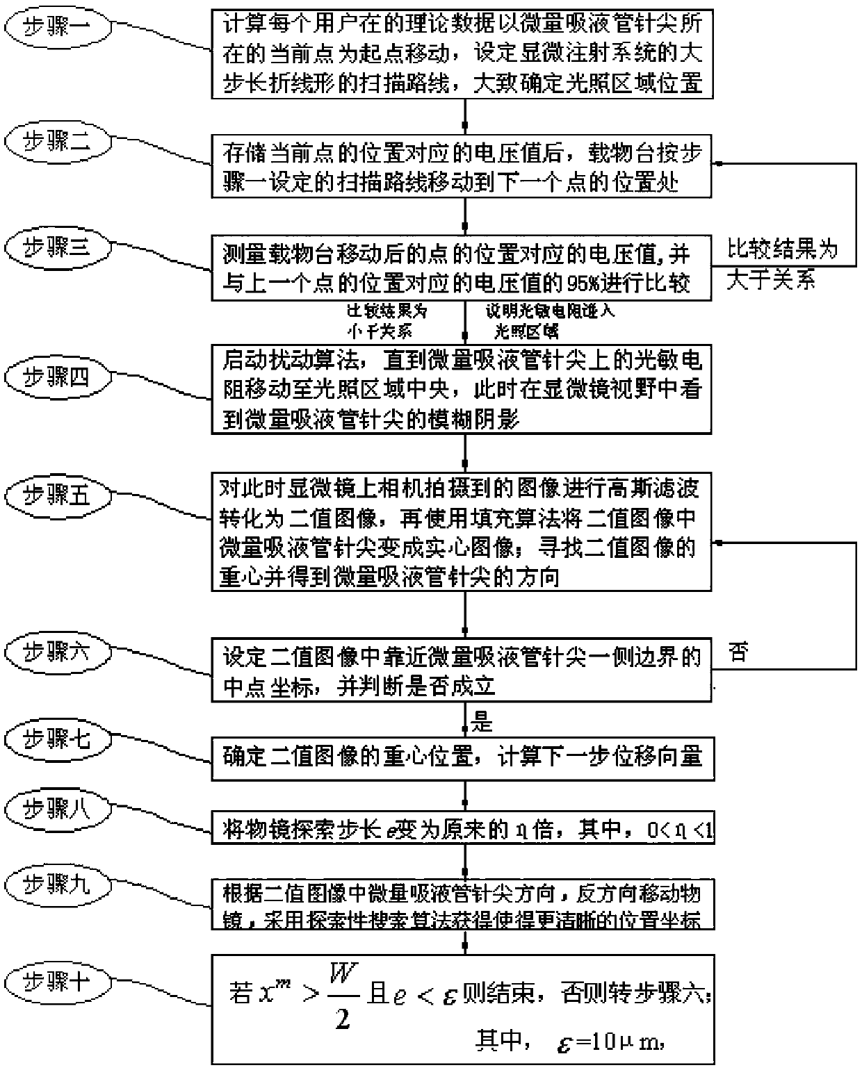
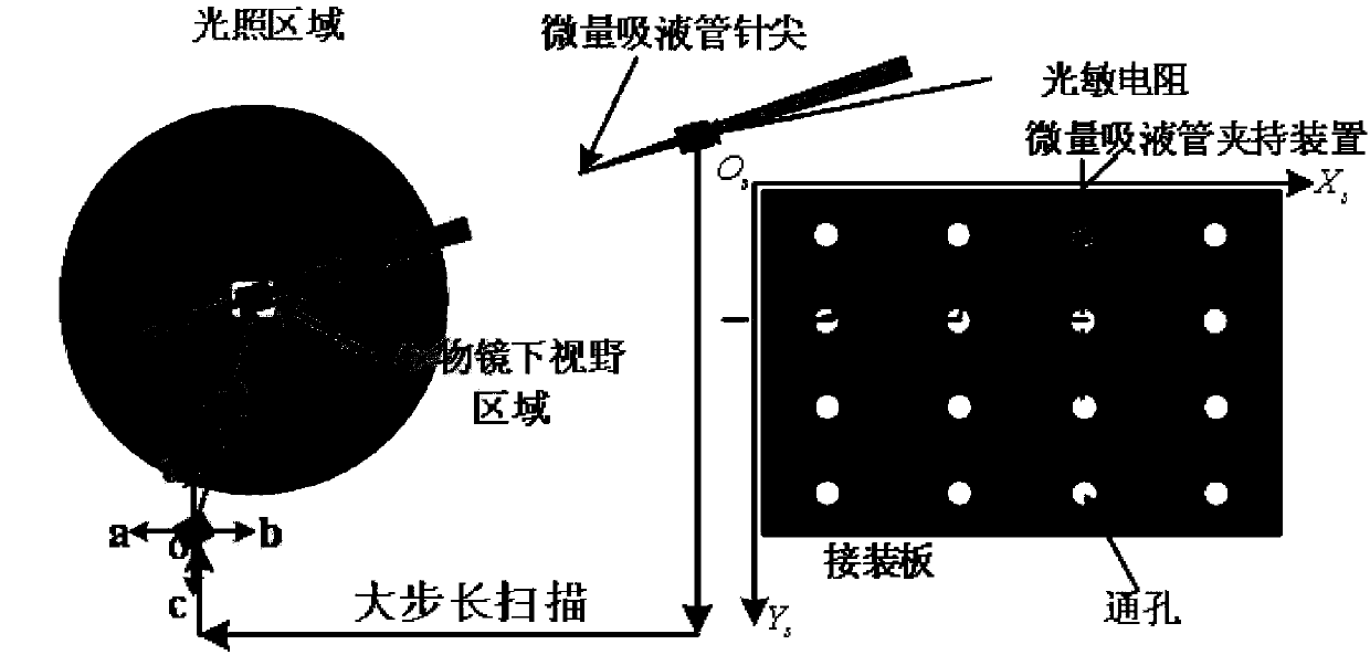
[0034] The large-scale automatic positioning method of the micropipette needle tip in the robot-assisted microinjection system of this embodiment, the large-scale refers to, compared with the existing needle tip positioning method when the initial position of the needle tip is a 4mm cube near the field of view , the allowable initial position range is expanded to 114mm×75mm×4mm, 114mm×75mm×4mm specifically means that the moving range of the stage on the horizontal plane is 114mm long and 75mm wide, and the moving range of the microscope objective lens in the vertical direction is 4mm . combine figure 1 As shown, the method is realized through the following steps: after the photoresistor is installed on the micropipette and the camera is installed on the microscope,

[0035] Step 1. Move the tip of the micropipette from the right side of the microscope field of view to the illuminated area, and move from the current point where the tip of the micropipette is located as the sta...

specific Embodiment approach 2

[0052] The difference from the specific embodiment 1 is that, in the large-scale automatic positioning method of the micropipette needle tip in the robot-assisted microinjection system of the present embodiment, the process of the disturbance algorithm described in step 4 is as follows:

[0053] Step 41. Move the stage to the left, right, front, and back (the left, right, front, and back directions mentioned here are determined relative to the position of the current point in the field of view of the microscope) by a small amount. Distance to four points a, b, c, d, and measure the voltage value of each point;

[0054] Step 42, according to Calculate the estimated value of the voltage gradient at the current position; and define the intermediate variable s=diag{q,q}grad f(o(k)) ∞ -Δp,

[0055] If s≤0, then

[0056] If s>0, then o(k+1)=o(k)+diag{q,q}grad f(o(k)),

[0057] If the voltage values ​​at the four points a, b, c, and d are all greater than the voltage measured ...

specific Embodiment approach 3

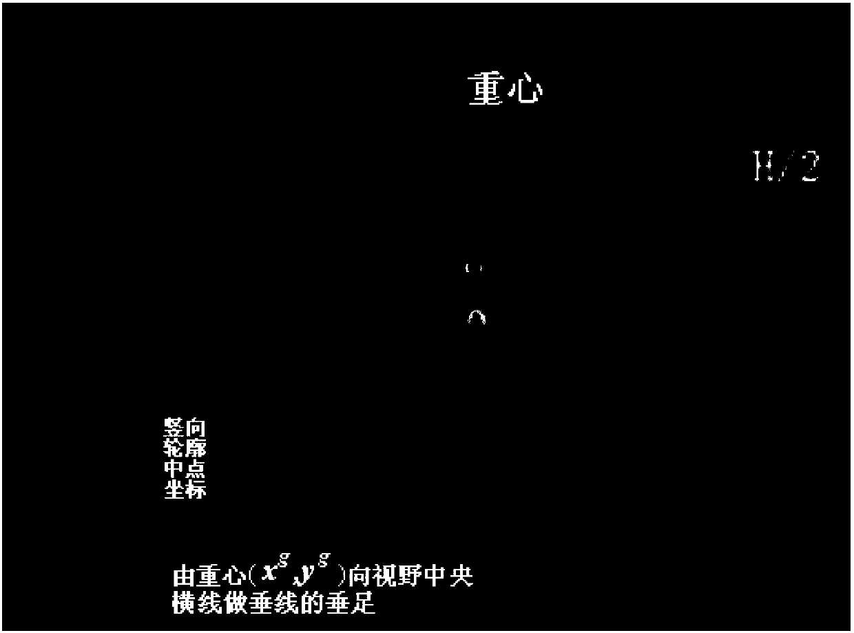
[0060] The difference from Embodiment 1 or Embodiment 2 is that the process of determining the center of gravity position of the image described in step 7 is as follows: Determine the coordinates of the center of gravity of the image (x g ,y g ), get the next step displacement vector mobile stage;

[0061] in, I(x,y) represents the pixel intensity at point (x,y); represents half the width of the field of view, t x and t y stands for displacement gain.


PUM


Abstract

The invention discloses a wide-range automatic positioning method of a robot assisted microinjection system medium trace pipette needle point, and belongs to the field of microinjection system positioning. The needle point only can be manually controlled to be moved to a specific position in a microinjection process, and only a blurred needle point image is captured. According to the wide-range automatic positioning method of the robot assisted microinjection system medium trace pipette needle point, a large-step long-scanning method is adopted outside an illumination area, a photoresistor is installed on a trace pipette, illumination information outside a view field is obtained through a bleeder circuit, after the photoresistor enters the illumination area, large-step long-scanning is terminated, and a perturbation algorithm is started, so that the photoresistor moves to the center of the illumination area. An objective table and an objective lens are adjusted repeatedly according to the contour direction of the image, so that the needle point can be finally positioned to the needle point to obtain a clear image. According to the method disclosed by the invention, the needle point can be quickly positioned to obtain the clear needle point image, and the positioning speed is increased by about five times compared with a traditional manual positioning method.

Description

technical field [0001] The invention relates to a large-scale automatic positioning method for the needle point of a micropipette in a robot-assisted microinjection system. Background technique [0002] During the microinjection process, the first step is to move the needle tip to a specific position for subsequent manipulations. However, most of the traditional needle tip positioning is done manually, which requires long-term training for operators and is not efficient in practical applications. The needle tip localization method proposed before also has certain limitations: first, since there is no feedback outside the field of view, the initial position of the needle tip before positioning is required to be very close to the field of view; in addition, the previous method only considers the focus alignment However, the actual situation is often out of focus, so only a blurred image of the needle can be captured, which makes it very difficult to detect and track the needl...

Claims


Application Information

Patent Timeline
Patent Type & Authority Patents(China)
IPC IPC(8): C12M1/26
CPCC12M33/04
Inventor 高会军庄松霖林伟阳张格非叶超尚忻忻
Owner 宁波智能装备研究院有限公司
Why Eureka
Try Eureka