Vehicle side impact simulation test structure and test method thereof
A side impact and simulation test technology, applied in vehicle testing, impact testing, machine/structural component testing, etc., can solve the problems of expensive prototype vehicles, roughness, product development obstacles, etc., to achieve high test efficiency and save development costs. , the effect of improving the accuracy
- Summary
- Abstract
- Description
- Claims
- Application Information
AI Technical Summary
Problems solved by technology
Method used
Image

Examples
Embodiment 1
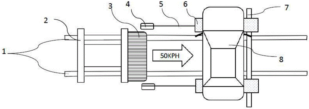
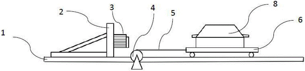
[0025] Such as figure 1 , figure 2 As shown, the vehicle side impact simulation test structure includes an acceleration slide 10, a slide track 1 and a body-in-white 8, and the bottom of the body-in-white 8 is respectively provided with support plates 6 where the front and rear axles should be located. A crossbeam 7 perpendicular to the slide track 1 is connected between the support plates 6. The crossbeam 7 is slidably arranged above the slide track 1 and makes the bottom of the body in white 8 parallel to the horizontal plane. The mutual fixing of the body in white 8 and the support plate 6 The position is consistent with the position where the body and chassis system of the actual vehicle are connected. The support plate 6 is parallel to the slide track 1 and the end of the support plate 6 close to the acceleration slide 10 is respectively connected with a brake mechanism 4 using a rope 5, the rope 5 is parallel to the slide track 1, and the brake mechanism 4 is transmitt...
Embodiment 2
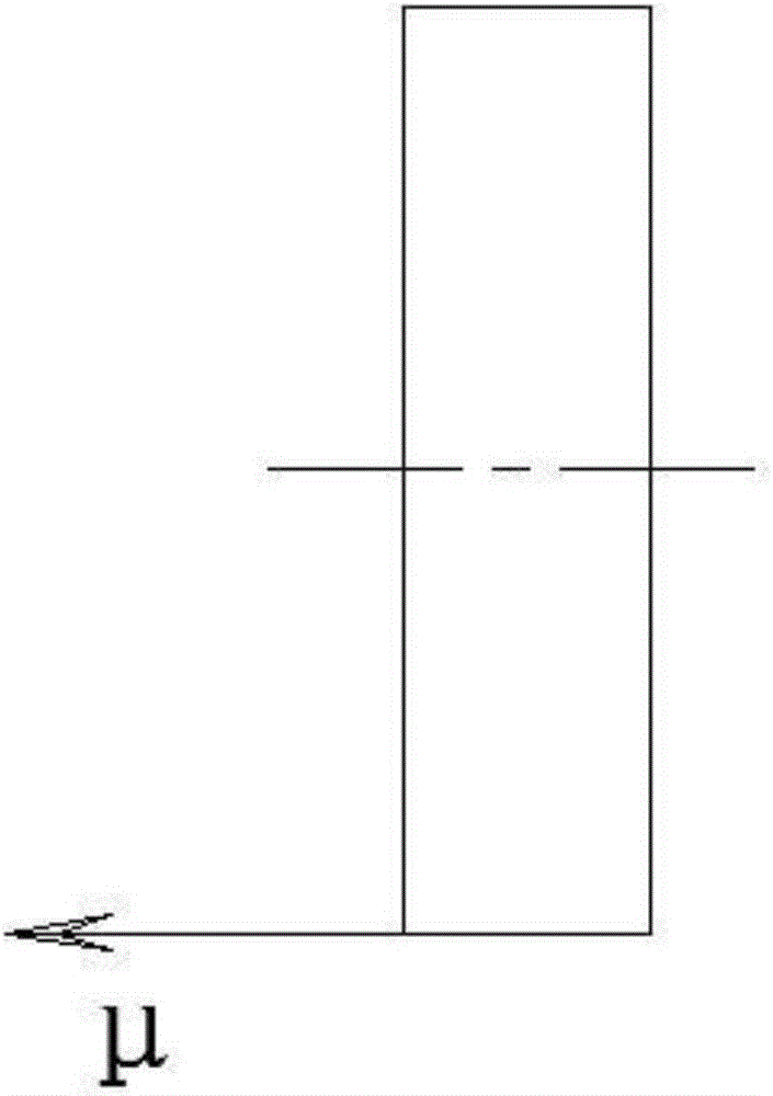
[0035] Such as Figure 4 As shown, the bullet car is an MDB angle bullet car 9. For the angled side impact simulation, taking the American standard FMVSS 214 as an example, the MDB angled bullet car 9 has an angle. Similarly, the MDB angled bullet car 9 is counterweighted according to the standard definition. The symmetrical center line of the body-in-white 8 in the figure and The center line of symmetry of the acceleration slide 10 is at an included angle of 63 degrees, and the body-in-white 8 is fixed on the support plate 6 at a standard defined angle. Similarly, the support plate 6 is parallel to the horizontal plane, that is, it can slide on the horizontal plane, and is controlled by the rope 5 and the brake. Mechanism 4 traction, brake mechanism 4 can set the traction force when releasing the rope 5, in the specific test, the set traction force can be the actual friction force between the wheel and the ground, can be obtained by actual measurement, and can also be obtaine...
Embodiment 3
[0041] Such as Figure 6 As shown, the bullet cart is a pillar-impact bullet cart 11, the pillar-impact bullet cart 11 is integrated with the acceleration slide 10, and the collision execution part is a collision pillar. Others are the same as embodiment 1.
[0042] For the side column impact test, such as the test of EURO-NCAP (European New Car Evaluation), that is, the collision column is stationary, and the vehicle collides with the collision column at a specified speed and angle, which is the same as the above-mentioned dynamic deformable barrier ( MDB) impacting the side of a stationary vehicle is different, but can also be simulated with the present invention. Such as Figure 6 , Figure 7 As shown, the acceleration slide table 10 and the column-impact bullet car 11 are always connected together. The front end of the column-impact bullet vehicle 11 is provided with a collision column with a size specified in the standard. When the set collision speed V0 is reached, th...
PUM
 Abstract
Description
Claims
Application Information
 - Generate Ideas
- Intellectual Property
- Life Sciences
- Materials
- Tech Scout
- Unparalleled Data Quality
- Higher Quality Content
- 60% Fewer Hallucinations
Browse by: Latest US Patents, China's latest patents, Technical Efficacy Thesaurus, Application Domain, Technology Topic, Popular Technical Reports.
© 2025 PatSnap. All rights reserved.Legal|Privacy policy|Modern Slavery Act Transparency Statement|Sitemap|About US| Contact US: help@patsnap.com