
Switch reluctance machine power converter correlation analysis and fault diagnosis method

A technology of switched reluctance motors and power converters, which is applied in the direction of measuring electrical variables, instruments, and measuring electricity, and can solve problems such as empirical, faulty phase current distortion, and heating

Active Publication Date: 2017-02-08
CHINA UNIV OF MINING & TECH
View PDF7 Cites 8 Cited by
  • Summary
  • Abstract
  • Description
  • Claims
  • Application Information

AI Technical Summary

Problems solved by technology

The power converter is the key actuator of the switched reluctance motor system. Its fault will cause the fault phase current to be distorted, making the motor output uneven, which will affect the performance of the entire system and the service life of the motor.
The power switch tube works in the high-frequency switching state for a long time, and it is easy to suffer from the current impact when it is turned off, with large loss and serious heat generation. It is the weakest part of the power converter that is most prone to failure.
At present, it is mainly to protect the power switch tube of the power converter by implementing measures such as overcurrent, overvoltage and overheating, but this method is only effective when the fault develops to a certain extent, and due to different fault protection conditions of the motor The determination of the threshold is difficult and empirical, and cannot be used for quantitative fault diagnosis
In addition, compared with the sinusoidal AC current flowing in the traditional AC motor, the non-sinusoidal intermittent unidirectional current flowing in each phase winding of the SRM, so the fault diagnosis method of the power converter of the traditional AC motor cannot be directly applied to the switching magnetic field. Fault Diagnosis of Power Converter of Resistance Motor

Method used


Image

  • Switch reluctance machine power converter correlation analysis and fault diagnosis method
  • Switch reluctance machine power converter correlation analysis and fault diagnosis method
  • Switch reluctance machine power converter correlation analysis and fault diagnosis method

Examples


Embodiment Construction

[0038] An embodiment of the present invention will be further described below in conjunction with the accompanying drawings.

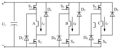
[0039] like figure 1As shown, it is the main circuit of the asymmetrical half-bridge power converter of the three-phase switched reluctance motor. Each phase of the three-phase asymmetrical half-bridge power converter has two main switches and two freewheeling diodes, A phase, Phase B and Phase C are connected in parallel to the positive pole "+" and negative pole "-" of the power supply. where the chopper tube S of phase A 1 One end is connected to the positive pole "+" of the power supply, and the chopper tube S 1 The other end is connected to one end of the A-phase winding, and the position conduction tube S 2 One end is connected to the negative pole "-" of the power supply, and the position conduction tube S 2 The other end is connected to the other end of the A-phase winding, and the freewheeling diode D 1 One end is connected to the positiv...


PUM


Abstract

The present invention discloses a switch reluctance machine power converter correlation analysis and fault diagnosis method. The method collects the phase current information of the whole period of a switch reluctance machine power converter to take the mean value of the phase current signals as an opening fault characteristic quantity; and the phase current signals are moved to the same phase, and the obtained signals are subjected to denoising processing through the wavelet analysis. The correlation coefficients of the processed phase current signals in the related broken interval are configured to detect the short circuit faults and identify the fault phase; the correlation coefficients of the current signals in the phase opening interval are configured to locate the short circuit power device to complete the fault diagnosis of the power converter. The switch reluctance machine power converter correlation analysis and fault diagnosis method is suitable for switch reluctance machine power converters with a plurality of number of phases and a plurality of topological structures is accurate in diagnosis and good in engineering application values.

Description

technical field [0001] The invention relates to a correlation analysis fault diagnosis method for a switched reluctance motor power converter, in particular to a correlation analysis fault diagnosis method for a power converter of a switched reluctance motor with various phase numbers and multiple topological structures. Background technique [0002] The high reliability of the switched reluctance motor system enables it to work in harsh environments. Research on fault diagnosis technology for the switched reluctance motor system can further improve the fault tolerance of the motor system under severe working conditions. The power converter is the key actuator of the switched reluctance motor system, and its failure will cause the distortion of the fault phase current, resulting in uneven output of the motor, which will affect the performance of the entire system and the service life of the motor. The power switching tube works in a high-frequency switching state for a long ...

Claims


Application Information

Patent Timeline
IPC IPC(8): G01R31/02G01R29/16
CPCG01R29/16G01R31/50
Inventor 陈昊史先强韩国强
Owner CHINA UNIV OF MINING & TECH
Learn More