Energy-saving acidic gas re-absorption technology matching with coal water slurry gasification
A re-absorption and energy-saving technology, applied in the direction of climate sustainability, combustible gas purification, removal of gas pollutants, etc., can solve the problem of reduced energy consumption of thermal regeneration system and external cooling consumption, and increased load of gas absorption section , increase in equipment investment and other issues, to achieve the effect of reducing the amount of circulating methanol, reducing load, reducing power consumption and equipment investment
Active Publication Date: 2017-02-15
SINOPEC NINGBO ENG +2
View PDF8 Cites 0 Cited by
- Summary
- Abstract
- Description
- Claims
- Application Information
AI Technical Summary
Problems solved by technology
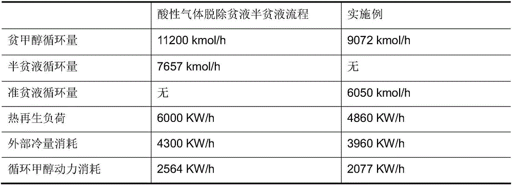
The acid gas removal process of lean liquid and semi-lean liquid reduces the heat regeneration system load and external refrigeration consumption to a certain extent, but due to the impact of semi-lean liquid on CO 2 The reabsorption capacity of the gas is limited, in order to ensure the absorption effect, a large amount of semi-poor liquid is required in the CO 2 Circulation between the abs
Method used
View moreImage
Smart ImageViewing Examples
Examples
 PUM
 Abstract
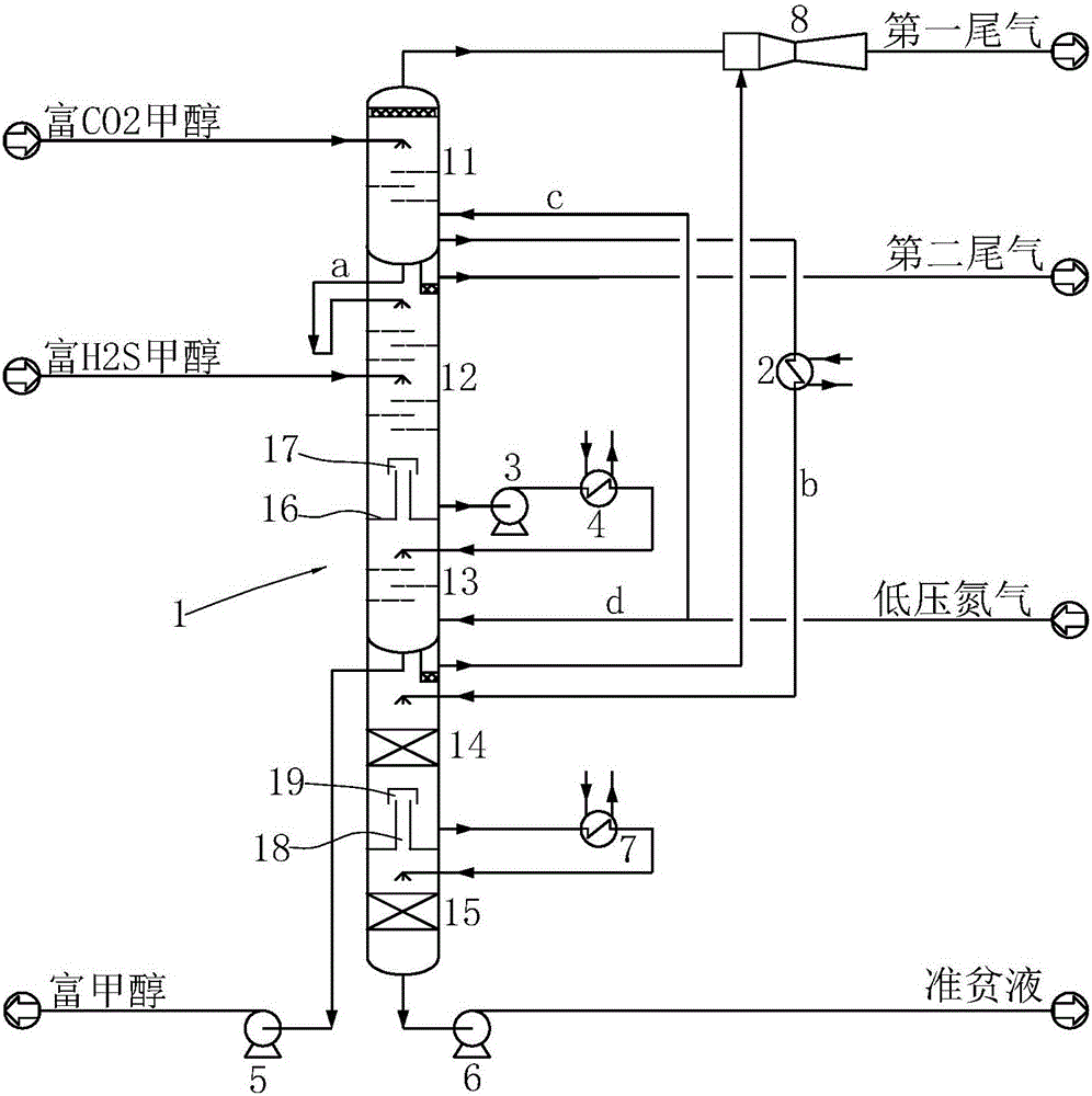
The invention relates to an energy-saving acidic gas re-absorption technology matching with coal water slurry gasification. The technology comprises the following steps: CO2-rich methanol enters a CO2-rich methanol stripping segment and undergoes reduced pressure flash evaporation, first nitrogen flow is also stripped, and separated first tail gas is sent to a gas ejector; first flow of semi-lean methanol enters a tail gas re-absorption segment; second flow of semi-lean methanol enters a quasi-lean solution generation segment upper segment and undergoes reduced pressure flash evaporation, a separated gas phase is extracted by the gas ejector, and a methanol solution enters a quasi-lean solution generation segment lower segment and undergoes flash evaporation; and a gas phase obtained after the flash evaporation enters the quasi-lean solution generation segment upper segment, a quasi-lean solution enters the tail gas re-absorption segment and undergoes flash evaporation and stripping, the released gas phase is washed by the first flow of semi-lean methanol, tail gas is discharged, a liquid phase is extracted, enters an N2 stripping segment and is stripped to obtain rich methanol which is sent to downstream, and the obtained gas phase enters the tail gas re-absorption segment and is washed by the first flow of semi-lean methanol.
Description
technical field [0001] The invention relates to an acid gas removal process, in particular to an energy-saving acid gas reabsorption technology matched with coal-water slurry gasification. Background technique [0002] Based on the current situation of my country's resources with more coal, less oil and less gas, the chemical industry using coal as raw material has developed rapidly in recent years. Coal is gasified at high temperature to produce H 2 The crude synthesis gas with CO as the main component is a suitable raw material for the production of C1 chemical industry and its derivatives. Coal-water slurry pressurized gasification technology is currently the most widely used due to its characteristics of wide adaptability to coal types, continuous and stable coal slurry transportation, high carbon conversion rate, pressurized gasification saving downstream gas compression energy consumption and low equipment investment. One of the new generation of advanced coal gasific...
Claims
Login to View More Application Information
Patent Timeline
 IPC IPC(8): B01D53/14C10K1/10
CPCB01D53/1406C10K1/003C10K1/10B01D2252/2021Y02P20/50
Inventor 唐永超施程亮亢万忠许仁春
Owner SINOPEC NINGBO ENG
Features
- R&D
- Intellectual Property
- Life Sciences
- Materials
- Tech Scout
- Unparalleled Data Quality
- Higher Quality Content
- 60% Fewer Hallucinations
Learn More Browse by: Latest US Patents, China's latest patents, Technical Efficacy Thesaurus, Application Domain, Technology Topic, Popular Technical Reports.
© 2025 PatSnap. All rights reserved.Legal|Privacy policy|Modern Slavery Act Transparency Statement|Sitemap|About US| Contact US: help@patsnap.com


