Pyrolysis gas conveying and spraying structure

A technology of pyrolysis gas and gas injection holes, which is applied in the direction of catalyst regeneration/reactivation, separation of dispersed particles, physical/chemical process catalysts, etc. It can solve problems such as large influence of system pressure, valve damage, and flow instability, etc., to achieve The effect of system pressure is small, the damage is reduced, and the spray is uniform

Inactive Publication Date: 2017-02-15
ACRE COKING & REFRACTORY ENG CONSULTING CORP DALIAN MCC
View PDF5 Cites 0 Cited by
  • Summary
  • Abstract
  • Description
  • Claims
  • Application Information

AI Technical Summary

Problems solved by technology

This patent realizes the on-line thermal desorption regeneration of the denitrification catalyst, but in practical application, the air volume of each air supply pipe is uneven and the flow rate is unstable, resulting in frequent actions of the air volume control valve, which not only easily damages the valve, but also causes pyrolysis. Uneven gas injection has a great influence on the system pressure

Method used


Image

  • Pyrolysis gas conveying and spraying structure
  • Pyrolysis gas conveying and spraying structure
  • Pyrolysis gas conveying and spraying structure

Examples


Embodiment Construction

[0022] The specific embodiment of the present invention will be further described below in conjunction with accompanying drawing:

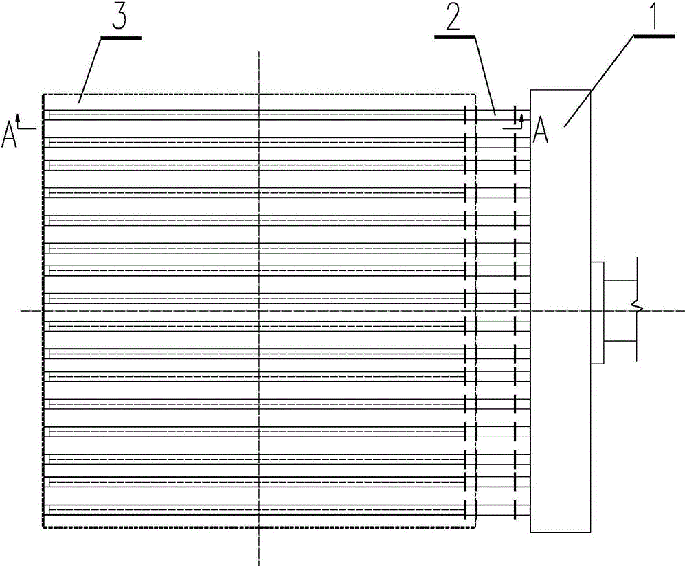
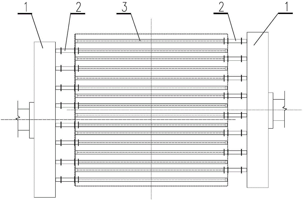
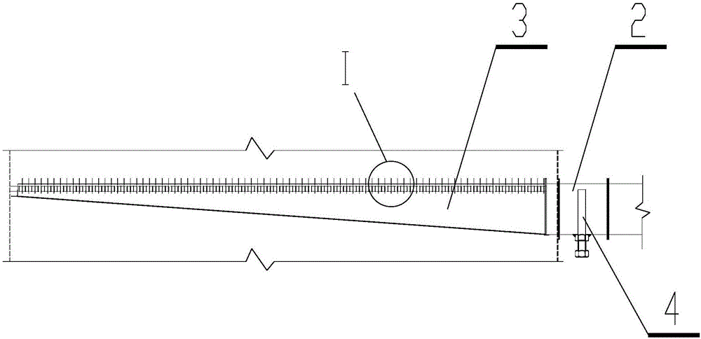
[0023] Such as figure 1 As shown, a pyrolysis gas delivery injection structure according to the present invention includes a pyrolysis gas buffer chamber 1, a flow regulating short pipe 2 and a pyrolysis gas branch pipe 3; the pyrolysis gas buffer chamber 1 is used to transfer an external heat source Buffer before introducing the pyrolysis gas branch pipe 3; the flow regulating short pipe 2 is used to connect the pyrolysis gas buffer chamber 1 and the pyrolysis gas branch pipe 3, and control the pressure and flow rate of the pyrolysis gas; the pyrolysis gas branch pipe 3 is a square cross-section gradient and one end of its large cross-section is connected to the flow regulating short pipe 2; the pyrolysis gas branch pipe 3 is provided with a gas injection hole 5, and a plurality of pyrolysis gas branch pipes 3 are evenly arranged side by side, an...


PUM


Abstract

The invention relates to a pyrolysis gas conveying and spraying structure. The structure comprises a pyrolysis gas buffer chamber, short flow adjusting tubes and pyrolysis gas branch tubes, wherein the pyrolysis gas buffer chamber is used for performing buffering before an external heat source is introduced into the pyrolysis gas branch tubes; the short flow adjusting tubes are used for connecting the pyrolysis gas buffer chamber with the pyrolysis gas branch tubes and controlling pressure and flow of the pyrolysis gas; each pyrolysis gas branch tube has a gradually changed square section, and the large-section end of the pyrolysis gas branch tube is connected with the corresponding short flow adjusting tube; gas spray holes are formed in the pyrolysis gas branch tubes, the multiple pyrolysis gas branch tubes are arranged in parallel uniformly and communicate with the pyrolysis gas buffer chamber through the short flow adjusting tubes respectively, and flow adjusting devices are arranged on the corresponding short flow adjusting tubes. The pyrolysis gas conveying and spraying structure is used for pyrolyzing a denitration catalyst online when used for removal of nitrogen oxides with an ammonia process, steps of repeated feeding and discharging of the denitration catalyst are omitted, the pyrolysis gas is sprayed uniformly and covers a wide range, the influence on system pressure is small, and continuous and stable operation of the system can be guaranteed.

Description

technical field [0001] The invention relates to the technical field of medium and low temperature flue gas desulfurization and denitrification, in particular to a pyrolysis gas delivery injection structure. Background technique [0002] When the reduction method is used to remove nitrogen oxides in the flue gas, the ammonia reduction method is often used, which is divided into SNCR method and SCR method according to the temperature and the presence or absence of catalyst; among them, the flue gas NH 3 -SCR denitration technology can be roughly divided into three types according to the temperature of the flue gas it treats: the first is high-temperature flue gas denitrification, and the temperature of the flue gas is The temperature of the flue gas is 200-300°C; the third is the low-temperature denitrification process, and the temperature of the flue gas is 120-220°C. The first high-temperature flue gas denitrification technology has been widely used in power plant denitrifi...

Claims


Application Information

Patent Timeline
Patent Type & Authority Applications(China)
IPC IPC(8): B01J38/02B01J38/04B01D53/96B01D53/90B01D53/56
CPCB01J38/04B01D53/8628B01D53/90B01D53/96B01J38/02
Inventor 霍延中尹华孙广明
Owner ACRE COKING & REFRACTORY ENG CONSULTING CORP DALIAN MCC
Why Eureka
Try Eureka