
A kind of external rotation feeding device used for large-scale thin-walled cylindrical piece counter-wheel spinning equipment

A technology of spinning equipment and thin-walled tubes, which is applied in the field of feeding devices, can solve problems such as poor versatility, high mold cost, and long manufacturing cycle, and achieve the effects of reduced production costs, good versatility, and reduced manufacturing cycle

Active Publication Date: 2018-07-06
HARBIN INST OF TECH
View PDF6 Cites 0 Cited by
  • Summary
  • Abstract
  • Description
  • Claims
  • Application Information

AI Technical Summary

Problems solved by technology

[0003] The purpose of the present invention is to solve the problems of high mold cost, poor versatility and long manufacturing cycle of the existing molded spinning equipment

Method used


Image

  • A kind of external rotation feeding device used for large-scale thin-walled cylindrical piece counter-wheel spinning equipment
  • A kind of external rotation feeding device used for large-scale thin-walled cylindrical piece counter-wheel spinning equipment
  • A kind of external rotation feeding device used for large-scale thin-walled cylindrical piece counter-wheel spinning equipment

Examples


specific Embodiment approach 1

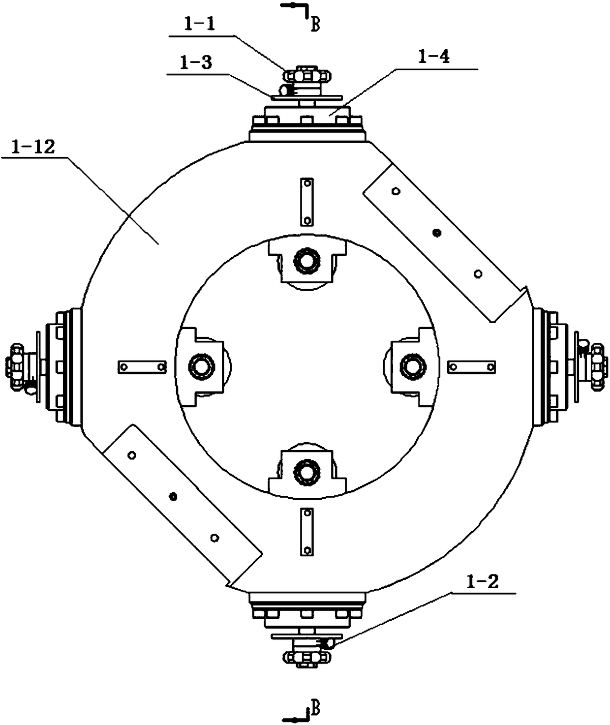
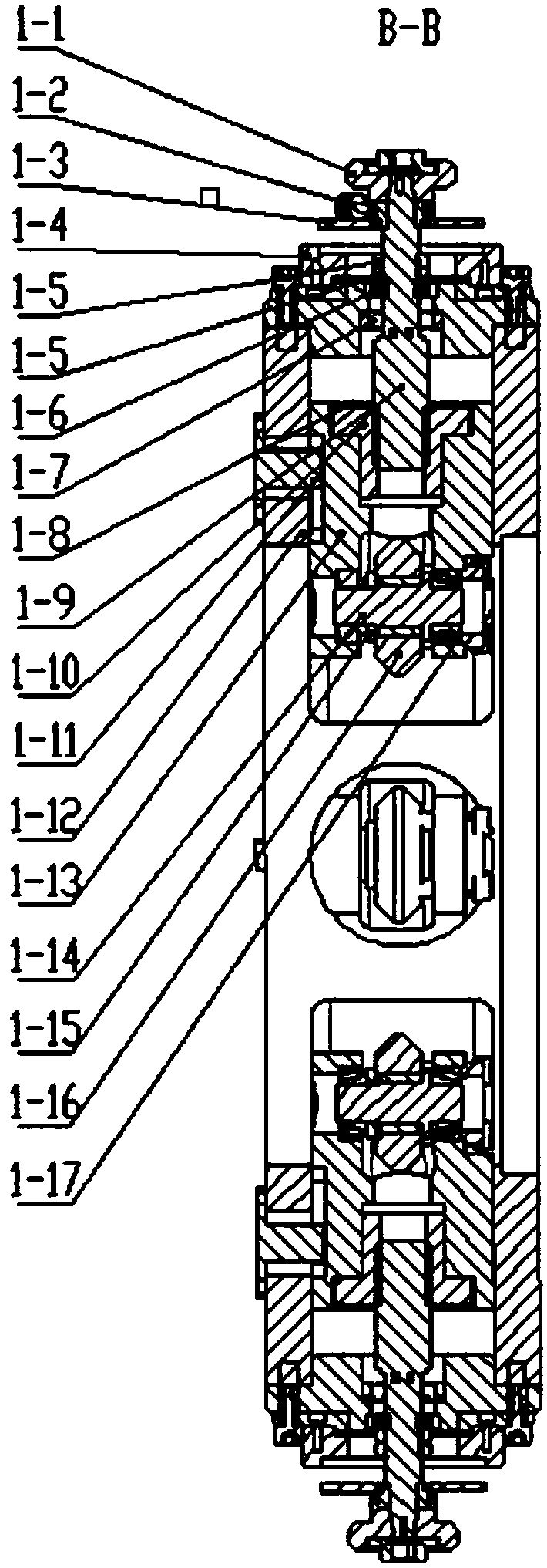
[0011] Specific embodiment one: combine 1 to Figure 5 Describe this embodiment, a kind of external rotation feeding device used for large-scale thin-walled cylindrical part counter-wheel spinning equipment in this embodiment includes a wheel base guide plate 1-12, a plurality of external rotation components and a plurality of external rotation Feed fixed seat assembly, a plurality of external rotation feed fixed seat assemblies are installed on the wheel seat guide disc 1-12, and the lower part of each external rotation feed fixed seat assembly is connected with an external rotation assembly;

[0012] Each external rotation assembly includes a rotary wheel 1-16, a rotary wheel shaft 1-14, a rotary wheel bearing spacer 1-15, a pair of tapered roller bearings 1-17, a lifting nut 1-10 and a rotary wheel seat 1-1. 13. The wheel seat 1-13 is installed on the wheel seat guide plate 1-12, the lifting nut 1-10 is seated on the wheel seat 1-13, and the wheel shaft 1-14 passes through ...

specific Embodiment approach 2

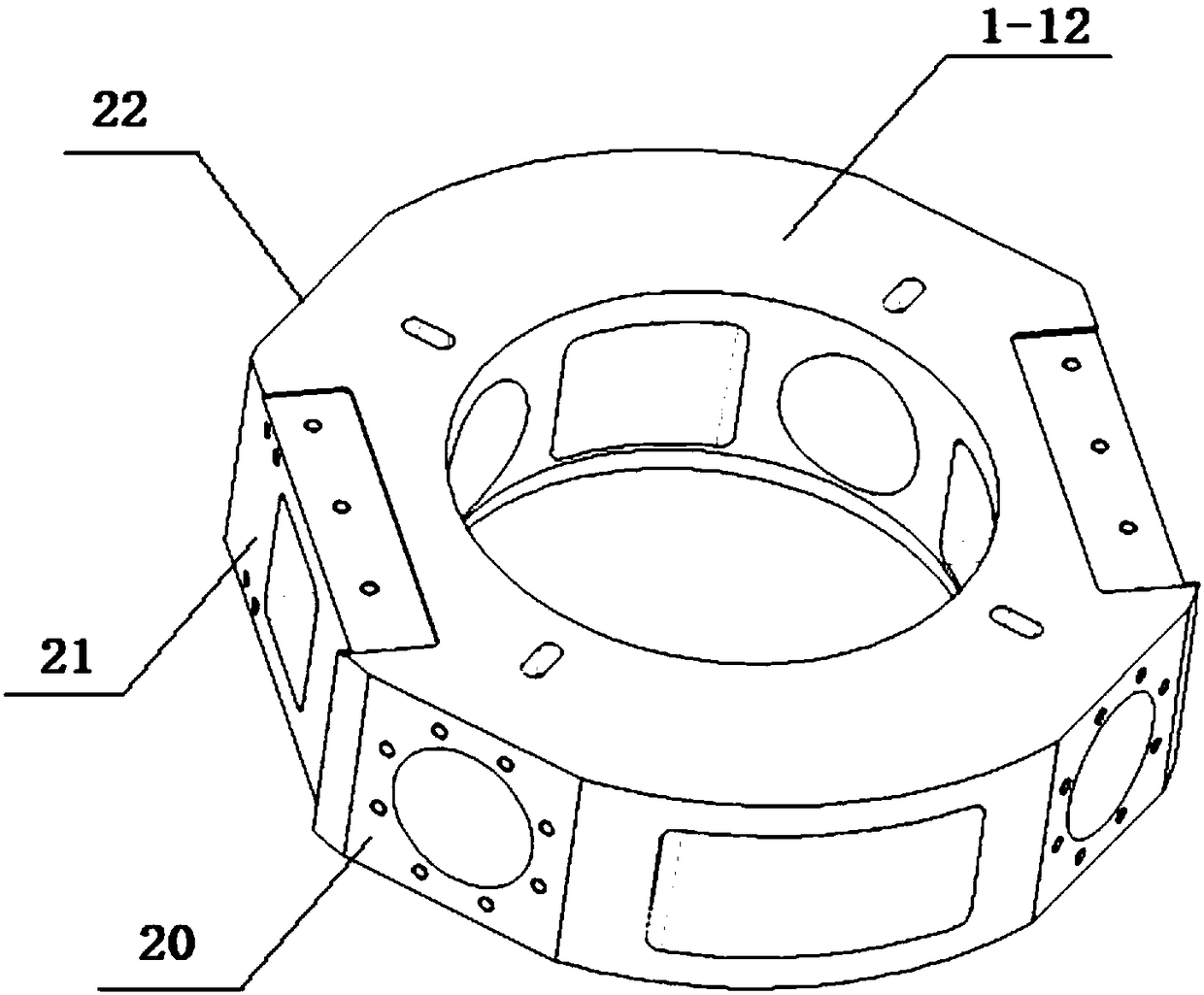
[0015] Specific implementation mode two: combination image 3 To illustrate this embodiment, the outer end face of the wheel seat guide plate 1-12 of this embodiment is a circular guide plate formed by two sections of arc end surfaces and two sections of planes arranged alternately. Concatenated sequentially. Such arrangement facilitates providing symmetrical spinning angles and directions. Other compositions and connections are the same as in the first embodiment.

specific Embodiment approach 3

[0016] Specific implementation mode three: combination image 3 Describe this embodiment, the three planes in this embodiment include a first rectangular plane 20, a second rectangular plane 21 and a third rectangular plane 22, the first rectangular plane 20, the second rectangular plane 21 and the third rectangular plane 22 Connected in sequence, the lengths of the first rectangular plane 20 and the third rectangular plane 22 are smaller than the length of the second rectangular plane 21 . With such arrangement, it is convenient to arrange the outer rotation components evenly. Other compositions and connections are the same as those in Embodiment 1 or Embodiment 2.


PUM


Abstract

The invention discloses an outer rotation feeding device of opposite roller spinning equipment for large-sized thin-walled cylindrical parts, and relates to outer rotation feeding devices. The outer rotation feeding device aims to solve the problems that existing mold spinning equipment is high in mold cost, poor in universality and long in manufacturing cycle. According to the outer rotation feeding device, a spinning roller base of each outer rotation assembly is installed on a spinning roller base guide disk, and lifting screw nut bases are arranged on the spinning roller bases; spinning roller shafts are installed on the corresponding spinning roller bases in a rotatable mode, spinning rollers are arranged on the corresponding spinning roller shafts in a sleeving mode, and spinning roller bearing distance sleeves are arranged on the corresponding spinning roller shafts in a sleeving mode; an outer rotation feeding screw of each outer rotation feeding fixed base assembly is installed in a corresponding lifting screw nut, and force measuring rings are arranged on the corresponding outer rotation feeding screws in a sleeving mode; outer rotation feeding fixed bases are buckled onto the corresponding spinning roller base guide disks; graduated discs are installed onto the corresponding outer rotation feeding fixed bases, and pointer turntables are installed onto the corresponding outer rotation feeding screws; rockers are fixedly connected with the upper portions of the outer rotation feeding screws; and the spinning rollers are arranged at the upper ends of the corresponding outer rotation feeding screws in a sleeving mode. The outer rotation feeding device is suitable for the opposite roller spinning equipment of the thin-walled cylindrical parts.

Description

technical field [0001] The invention relates to a feeding device, in particular to an external rotation feeding device used for wheel-to-wheel spinning equipment for large thin-walled cylindrical parts. Background technique [0002] Counter wheel spinning is an economical method for processing large-scale pipe fittings to manufacture large-diameter precision pipe fittings. Due to the high cost of tooling, this method will not lose its economy unless the counter wheel is used instead of the mandrel. By adjusting the radial distance of the wheel pair, pipes with any diameter and different thickness within a certain range can be processed, thus reducing the production cost of the core mold; Compared with that, the spinning deformation of the counter wheel is completed by the inner and outer symmetrical spinning wheel pairs, and the spinning pressure is reduced by half; due to the symmetry of the material flow, the deformation of the inner and outer layers of the billet is equiv...

Claims


Application Information

Patent Timeline
Patent Type & Authority Patents(China)
IPC IPC(8): B21D22/14
CPCB21D22/14
Inventor 徐文臣王森鹏单德彬杨川陈宇
Owner HARBIN INST OF TECH
Learn More