Selective laser sintering and melting equipment

A technology of laser sintering and melting equipment, which is applied to the improvement of process efficiency, additive manufacturing, additive processing, etc., can solve the problems of consumption of inert gas and increase of production cost, and achieve the effect of avoiding lens overheating and reducing production cost

Active Publication Date: 2017-02-15
CHONGQING UNIV
View PDF7 Cites 9 Cited by
  • Summary
  • Abstract
  • Description
  • Claims
  • Application Information

AI Technical Summary

Problems solved by technology

This will consume a large amount of inert g

Method used


Image

  • Selective laser sintering and melting equipment
  • Selective laser sintering and melting equipment
  • Selective laser sintering and melting equipment

Examples


Embodiment Construction

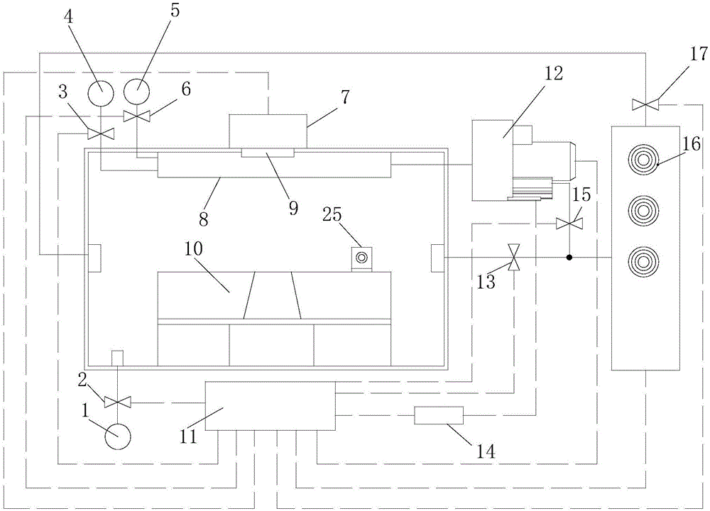
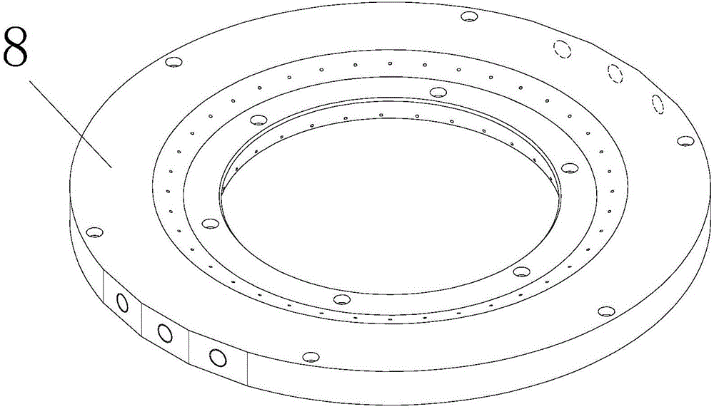
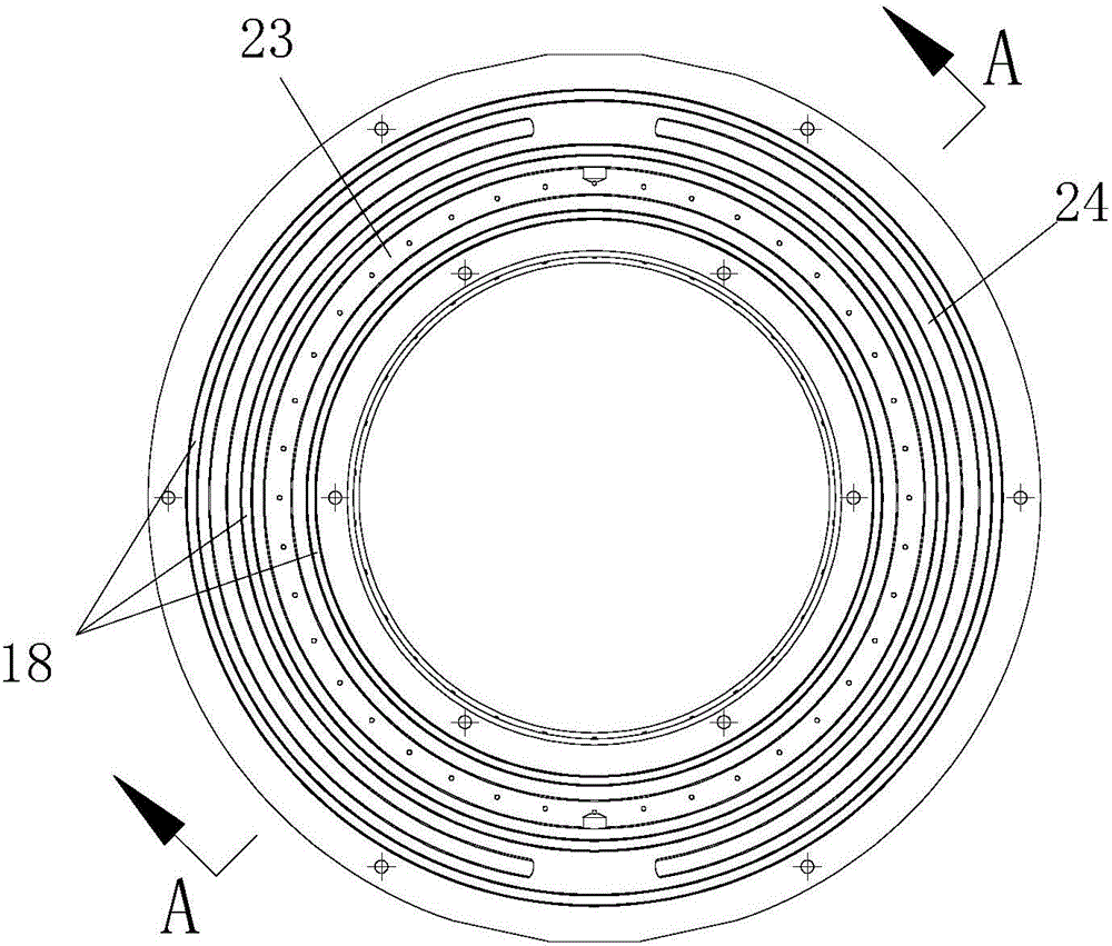
[0022] figure 1 It is a structural schematic diagram of the present invention. As shown in the figure, the selective laser sintering and melting equipment of this embodiment includes a sealed molding chamber, a laser vibrating mirror 7 arranged outside the sealed molding chamber, and a laser vibrating mirror 7 arranged on the surface of the sealed molding chamber for making the laser vibrating mirror 7 The projected laser enters the lens 9 in the sealed molding chamber, the part processing platform 10 arranged in the sealed molding chamber, the powder spreading scraper 25 for laying powder on the processing platform, fixed on the inner wall of the sealed molding chamber and An annular air curtain device 8 corresponding to the lens 9 and a gas source for providing gas to the annular air curtain device 8; the annular air curtain device 8 is provided with a central hole for the laser to pass through, surrounding The annular gas channel provided in the central hole, the air curta...


PUM


Abstract

The invention discloses selective laser sintering and melting equipment which comprises a sealing forming bin, a laser galvanometer arranged outside the sealing forming bin, a lens arranged on the surface of the sealing forming bin and used for enabling the laser projected from the laser galvanometer to enter the sealing forming bin, a part machining platform arranged in the sealing forming bin, a powder paving scraper used for paving powder on the machining platform, an annular gas curtain device fixed to the inner wall of the sealing forming bin and corresponding to the lens, and a gas source used for providing gas for the annular gas curtain. According to the selective laser sintering and melting equipment, a cone high-speed gas curtain wall can be formed around the inner surface of the lens, a clean space is formed around the inner surface of the lens, and metal powder in the forming bin can be effectively prevented from adhering to the surface of the lens. Meanwhile, the lens is prevented against dust and cooled through inert gas in the forming bin during the machining process of the equipment, so that a large amount of inert gas is saved, and the production cost is lowered.

Description

technical field [0001] The invention relates to the technical field of selective laser sintering and melting, in particular to a selective laser sintering and melting equipment. Background technique [0002] Most of the large-scale multi-station selective laser sintering and melting equipment put the galvanometer system outside, and use the multi-station laser galvanometer to scan the metal powder layer by layer and the multi-region splicing technology to form parts. This molding method has high molding efficiency and can form It has the advantages of large multifunctional special-shaped structure, and has the characteristics of many processing stations and long processing time. The inner surface of the airtight lens that allows the laser to enter the airtight molding chamber from the outside will be completely exposed to the environment full of metal dust. When the laser irradiates the dust attached to the lens, the high temperature generated by the powder melting will seri...

Claims


Application Information

Patent Timeline
IPC IPC(8): B22F3/105B33Y30/00
CPCB22F3/003B33Y30/00B22F10/00B22F12/49B22F10/32B22F10/28B22F12/70B22F12/20Y02P10/25
Inventor 张正文戴京伟徐仁俊刘飞张鹏王海亮
Owner CHONGQING UNIV
Why Eureka
Try Eureka