Annular polisher
A polishing machine, annular technology, applied in grinding/polishing equipment, optical surface grinder, metal processing equipment, etc., to achieve the effect of reducing equipment cost, improving polishing efficiency and reducing power consumption
- Summary
- Abstract
- Description
- Claims
- Application Information
AI Technical Summary
Problems solved by technology
Method used
Image

Examples
Embodiment 1
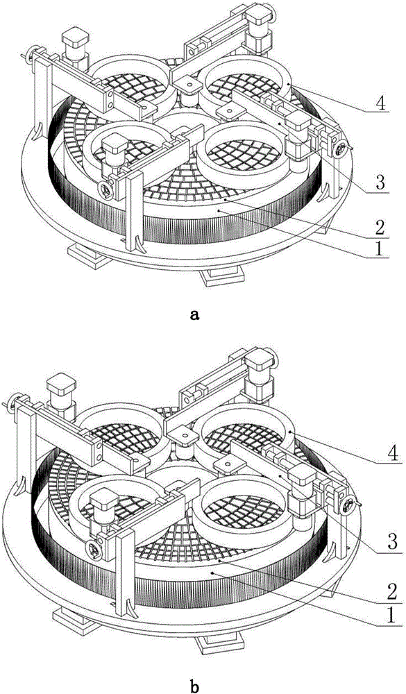
[0029] see figure 1 a, a ring polishing machine, including a turntable 1, a polishing disc 2, a limit roller mechanism 3 and a workpiece ring 4, the polishing disc 2 is also provided with a narrow groove, it is characterized in that the workpiece ring 4 The inner diameter is smaller than the width of the ring of the polishing disc 2, and the outer diameter is larger than the width of the ring of the polishing disc 2. The narrow groove divides the disc surface of the polishing disc into a plurality of small units, and the area variation trend of each small unit is along the direction of the polishing disc 2. The radius of becomes larger and then smaller from the center to the edge.
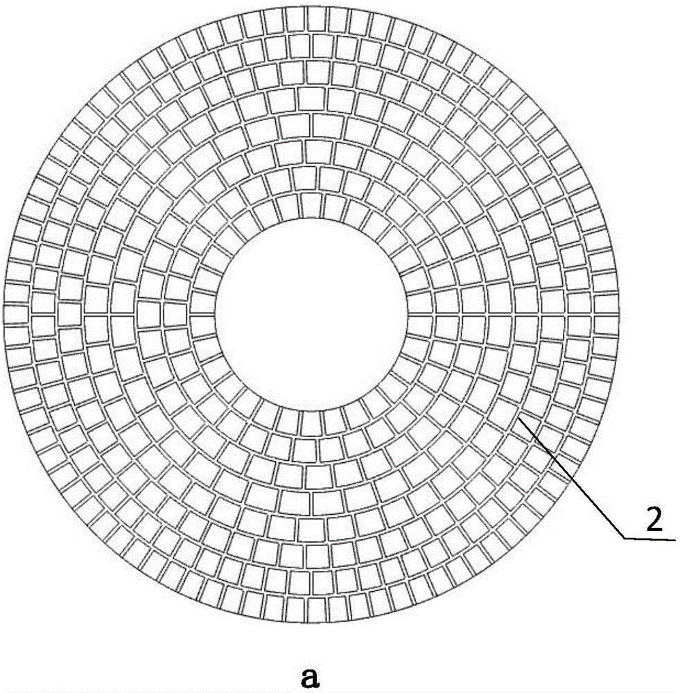
[0030] see figure 2 a and figure 2 b, figure 2 a and figure 2 b represents a groove shape, the narrow groove divides the surface of the polishing disc into multiple small units, and the area of each small unit tends to change from small to large and then small along the radius of the poli...
Embodiment 2
[0032] see figure 1 b, a ring polishing machine, including a turntable 1, a polishing disc 2, a limit roller mechanism 3 and a workpiece ring 4, the polishing disc 2 is also provided with a narrow groove, it is characterized in that the workpiece ring 4 The inner diameter is smaller than the width of the ring of the polishing disc 2, and the outer diameter is larger than the width of the ring of the polishing disc 2. The narrow groove divides the disc surface of the polishing disc into a plurality of small units, and the area variation trend of each small unit is along the direction of the polishing disc 2. The radius of becomes smaller from the center to the edge.
[0033] see figure 2 c and figure 2 d, figure 2 c and figure 2 d represents a groove shape, the narrow groove divides the disc surface of the polishing disc into multiple small units, and the area of each small unit tends to change along the radius of the polishing disc 2 from the center to the edge.
Embodiment 3
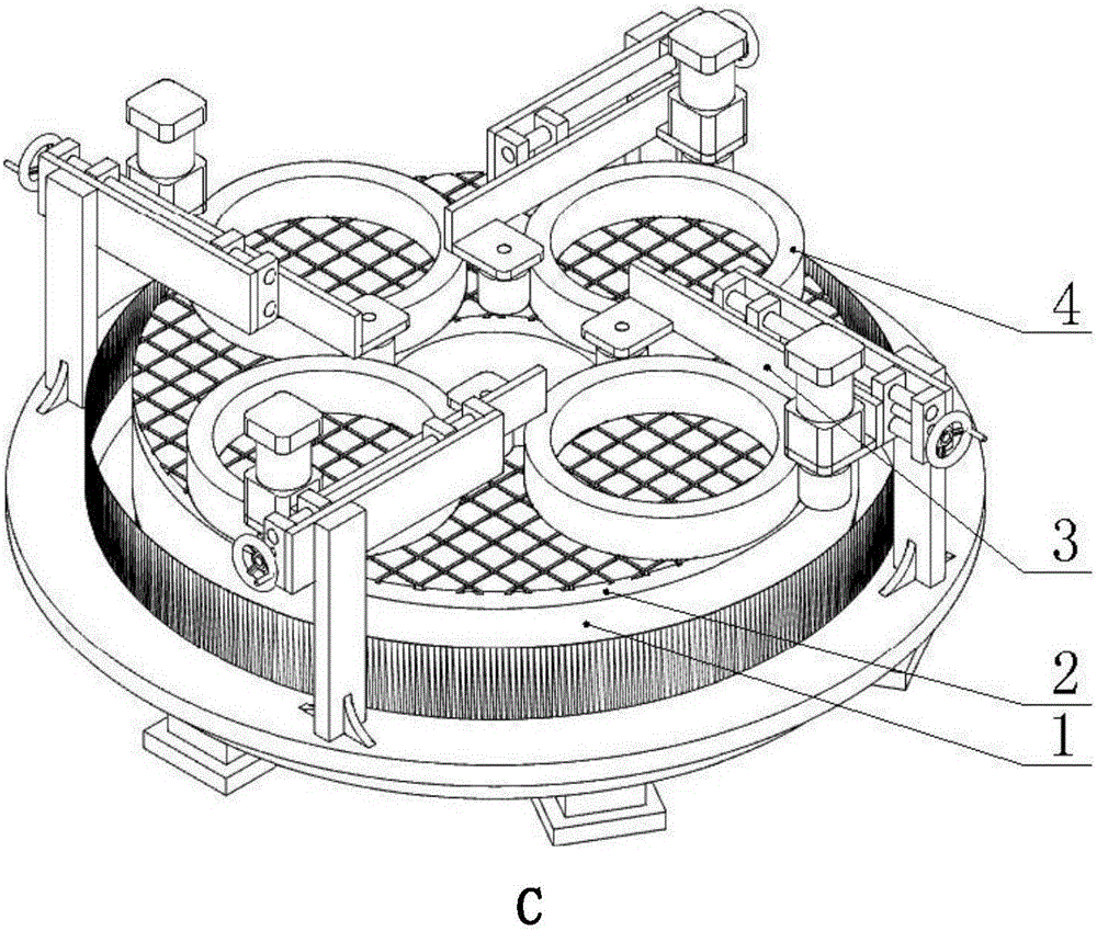
[0035] see figure 1 c, a ring polishing machine, including a turntable 1, a polishing disc 2, a limit roller mechanism 3 and a workpiece ring 4, the polishing disc 2 is also provided with a narrow groove, it is characterized in that the workpiece ring 4 The inner diameter is smaller than the width of the ring of the polishing disc 2, and the outer diameter is greater than the width of the ring of the polishing disc 2. The narrow groove divides the disc surface of the polishing disc into a plurality of small units, and the depth variation trend of the narrow groove is along the polishing disc 2. The radius changes from darker to lighter, then darker from the center to the edge.
[0036] see image 3 a, image 3 a is a schematic diagram of the groove depth, and the depth variation trend of the narrow groove is along the radius of the polishing disc 2 from the center to the edge from deep to shallow, and then to deep.
PUM
 Abstract
Description
Claims
Application Information
 - Generate Ideas
- Intellectual Property
- Life Sciences
- Materials
- Tech Scout
- Unparalleled Data Quality
- Higher Quality Content
- 60% Fewer Hallucinations
Browse by: Latest US Patents, China's latest patents, Technical Efficacy Thesaurus, Application Domain, Technology Topic, Popular Technical Reports.
© 2025 PatSnap. All rights reserved.Legal|Privacy policy|Modern Slavery Act Transparency Statement|Sitemap|About US| Contact US: help@patsnap.com