
On-vehicle structure

A technology of connecting points and structures, which is applied in the field of vehicle structures, and can solve problems such as device collision loads

Active Publication Date: 2017-02-15
TOYOTA JIDOSHA KK
View PDF8 Cites 4 Cited by
  • Summary
  • Abstract
  • Description
  • Claims
  • Application Information

AI Technical Summary

Problems solved by technology

Or, in terms of a collision in which only the right front part (or left front part) of the vehicle collides with the obstacle instead of the vehicle colliding head-on with the obstacle, the obstacle may enter deep inside the vehicle front space and be arranged in the front space The unit may be subjected to significant crash loads

Method used


Image

  • On-vehicle structure
  • On-vehicle structure
  • On-vehicle structure

Examples


Embodiment Construction

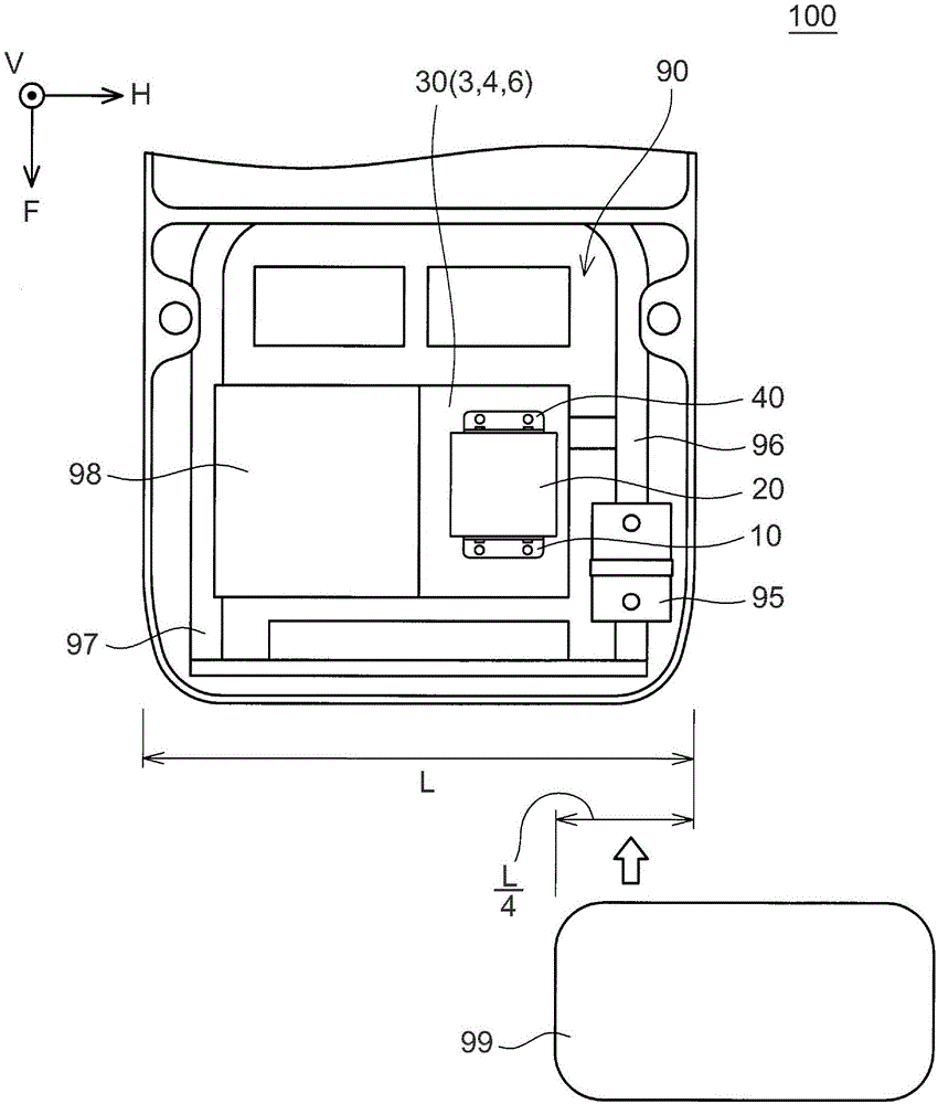
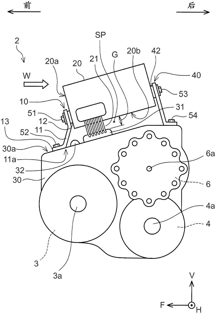
[0023] The vehicle-mounted structure of the first embodiment will be described with reference to the drawings. The vehicle-mounted structure 2 of the first embodiment is applied to a hybrid vehicle 100 including both the travel motor 3 and the engine 98 . The vehicle-mounted structure 2 is a structure in which the power control unit 20 for driving the motor 3 is fixed above the casing 30 . The case 30 accommodates the motor 3 , the power distribution mechanism 6 and the differential gear 4 . For simplicity of description, "power control unit 20" is abbreviated as "PCU 20" hereinafter. PCU stands for Power Control Unit.

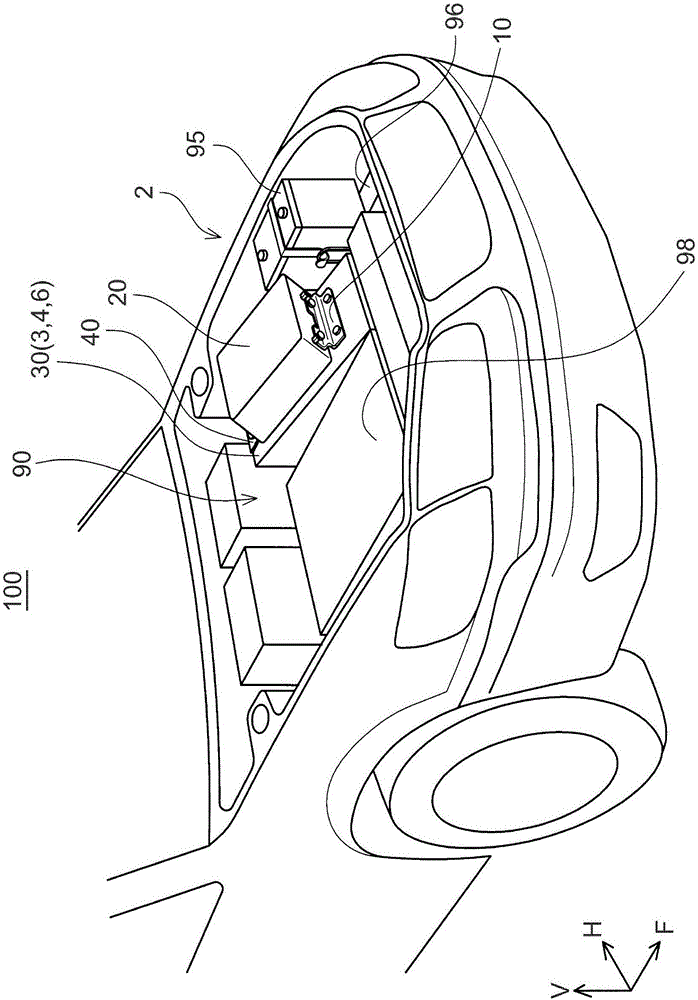
[0024] figure 1 with figure 2 The arrangement of devices in engine room 90 of hybrid vehicle 100 is shown. figure 1 is a view (plan view) of the engine compartment 90 seen from above, figure 2 It is a perspective view of the engine compartment 90 viewed obliquely from above. The engine compartment 90 of the hybrid vehicle 100 is located at the front o...


PUM


Abstract

An on-vehicle structure includes a housing of a motor and a power control unit. The power control unit is fixed by a front bracket and a rear bracket above the housing. A space is defined between a lower surface of the power control unit and the housing. The front bracket includes a base section and a support section. The support section is configured to contact with the housing before the lower surface of the power control unit contacts with an upper surface of the housing when the support section is collapsed rearward by a load applied to the power control unit from front.

Description

technical field [0001] The present invention relates to an on-vehicle structure for a power control unit that drives a motor for running (travel motor). Background technique [0002] A vehicle traveling using an electric motor includes a power control unit for driving the electric motor. It should be noted that the technology disclosed in this specification is not limited to application to electric vehicles, but can also be applied to hybrid vehicles and fuel cell vehicles. In addition, for simplification of description, "motor" will be simply referred to as "motor". [0003] The power control unit is typically an inverter that converts DC power output from the DC power supply into AC power. The power control unit may include a boost converter. Several types of vehicles provided with traveling motors include a motor and a power control unit located in the front space (engine compartment) of the vehicle. In this specification, according to the custom in the field of autom...

Claims


Application Information

Patent Timeline
Patent Type & Authority Applications(China)
IPC IPC(8): B60K1/00B60R16/02
CPCB60K1/00B60R16/02B60L15/007B60Y2306/01B60Y2410/115Y02T10/64Y02T10/72B60K28/14B60L3/0007B60Y2200/90B60L3/0084B60L15/20B60Y2410/10
Inventor 坂本优亮
Owner TOYOTA JIDOSHA KK
Features
  • Generate Ideas
  • Intellectual Property
  • Life Sciences
  • Materials
  • Tech Scout
  • Unparalleled Data Quality
  • Higher Quality Content
  • 60% Fewer Hallucinations
Learn More