Nozzle configuration mode of multi-rotor wing agricultural unmanned aerial vehicle and spraying system thereof
A configuration method and unmanned aerial vehicle technology, which is applied in the spraying system and agricultural aviation plant protection machinery industry, can solve the problems of increased droplet drift and complicated rotor wind field, so as to reduce the drift of liquid medicine, reduce environmental pollution, and avoid drift Effect
- Summary
- Abstract
- Description
- Claims
- Application Information
AI Technical Summary
Problems solved by technology
Method used
Image
Examples
Embodiment 1
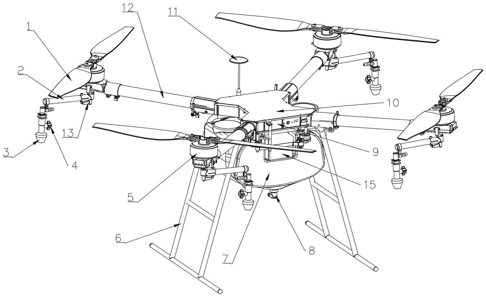
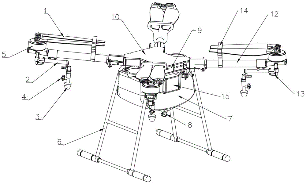
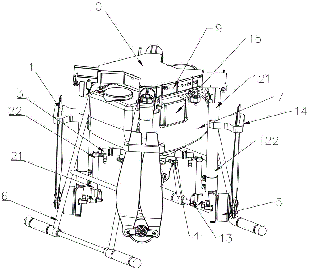
[0045] see Figure 1-Figure 3 , a four-rotor agricultural unmanned aerial vehicle spraying system of the present embodiment includes an unmanned aerial vehicle fuselage 10, a rotor arm 12, a rotor motor 5, a rotor 1, a spray bar 2, a nozzle 3, a medicine box 7, and a diaphragm pump (Fig. not shown) and nozzles (not shown). The root end 121 of the rotor arm is connected with the fuselage 10 of the drone, and the tip end 122 of the rotor arm is connected with the rotor motor 5 . The rotor 1 is installed above the rotor motor 5 . The root end 21 of the spray rod is fixed on the tip 122 of the rotor arm, the tip 22 of the spray rod (that is, the free end of the spray rod) is connected to the nozzle 3, the medicine box 7 is installed under the fuselage 10 of the drone, and the inside of the medicine box 7 The liquid medicine enters the spray pipe under the action of the diaphragm pump and sprays out from the nozzle 3. Among them, the spray rod and the nozzle constitute the spray...
Embodiment 2
[0053] see Image 6 , and the difference from Embodiment 1 is that this embodiment is the second nozzle configuration of the four-rotor agricultural UAV. For the four-rotor agricultural UAV in this embodiment, a spray bar 2 and a nozzle 3 are respectively arranged under each rotor 1; The length d21 is equal, the two spray bars are located on the same straight line, and the free ends of the two spray bars are all facing the inside of the fuselage; the length d22 of the two spray bars arranged at the lower part of the left and right rear rotors of the UAV equal, and satisfy d21≤d22, the two spray booms are located on the same straight line, and the free ends of the two spray booms are both facing the outside of the fuselage.
Embodiment 3
[0055] see Figure 7 , the difference from Embodiment 1 and Embodiment 2 is that this embodiment is the third nozzle configuration mode of the four-rotor agricultural UAV. For the four-rotor agricultural UAV in this embodiment, a spray head is respectively arranged under each rotor; The directions of the free ends are all towards the left side of the fuselage; the two spray bars arranged on the lower part of the left and right rear rotors of the UAV are located on the same straight line, and the directions of the free ends of these two spray bars are all towards the right side of the fuselage; at the same time , the length d31 of the two spray bars arranged at the lower part of the left front and right rear rotors of the UAV is equal, and the length d32 of the two spray bars arranged at the lower part of the right front and left rear rotors of the UAV is equal, and d32≤d31 is satisfied.
PUM
 Abstract
Description
Claims
Application Information
 - R&D
- Intellectual Property
- Life Sciences
- Materials
- Tech Scout
- Unparalleled Data Quality
- Higher Quality Content
- 60% Fewer Hallucinations
Browse by: Latest US Patents, China's latest patents, Technical Efficacy Thesaurus, Application Domain, Technology Topic, Popular Technical Reports.
© 2025 PatSnap. All rights reserved.Legal|Privacy policy|Modern Slavery Act Transparency Statement|Sitemap|About US| Contact US: help@patsnap.com


