
Assembly type prefabricated structure wallboard unit and connecting joints thereof

A prefabricated structure, prefabricated technology, applied in the direction of walls, building components, building structures, etc., can solve the problem of failure to achieve the principle of seismic structure, the connection of prefabricated concrete structures does not achieve structural performance, and the connection nodes are not well implemented. Seismic design principles, etc.

Inactive Publication Date: 2017-02-15
刘祥锦
View PDF19 Cites 7 Cited by
  • Summary
  • Abstract
  • Description
  • Claims
  • Application Information

AI Technical Summary

Problems solved by technology

[0008] (3) The technology of using auxiliary material steel plate or section steel for connection, such as "A Connection Node of Prefabricated Concrete Shear Wall Structure Wall Panel Members" disclosed in the patent document with the authorized announcement number CN 202561554 B, which has a certain length of connection The profiled steel should be placed in the center of a closed rectangular stirrup cage with a spacing of less than 300mm, and the periphery and both ends are hindered by prefabricated components or reserved steel bars, making construction very difficult, and there is no explanation on how to deal with the profiled steel at the intersection of the wall; another example: Authorized announcement number CN 204174785 U's patent literature discloses "a prefabricated wall panel unit upper and lower connection structure", the steel plate connection is a point connection; the two technical solutions disclosed above do not provide the connection method at the edge member of the shear wall, No comprehensive joint connection technology is proposed, nor is the seismic structural principle of "strong joints, weak members"
[0009] (4) There are still some that only solve the local connection technology, and the practicability may be limited by relevant specifications, such as the "U-shaped closed rib connection structure of the horizontal joint of the assembled shear wall structure" disclosed in the patent document of the authorized announcement number CN 102168455 B. Whether the steel bar connection method meets the relevant national regulations on the tension of the steel bar, whether it is seismically resistant, does not provide the connection method at the edge members of the shear wall, and does not achieve the earthquake-resistant building structure principle of "strong nodes, weak members"
[0015] (2) There are only partial connection technologies for node connections, and the seismic design principles of "strong nodes and weak components" are not well realized for connection nodes;
[0016] (3) The connection nodes require the use of section steel auxiliary connection, because entering the section steel structure and adding factors to solve the increase in the connection between the section steel and the concrete structure have to be dealt with, and the production process cannot be truly simplified;
[0017] (4) The on-site construction technology and procedures are not simple enough, and formwork needs to be installed on the post-cast concrete part, which has not realized "complex production factoryization, simple labor on-site activities"
[0018] (5) The connection of prefabricated concrete structures does not achieve the same structural performance as that of cast-in-place concrete structures, which affects the scope of application of prefabricated buildings and severely restricts the promotion of building industrialization to a larger proportion.

Method used


Image

  • Assembly type prefabricated structure wallboard unit and connecting joints thereof
  • Assembly type prefabricated structure wallboard unit and connecting joints thereof
  • Assembly type prefabricated structure wallboard unit and connecting joints thereof

Examples


Embodiment Construction

[0115] The present invention will be described in further detail below with reference to the embodiments and the accompanying drawings, but the embodiments of the present invention are not limited thereto.

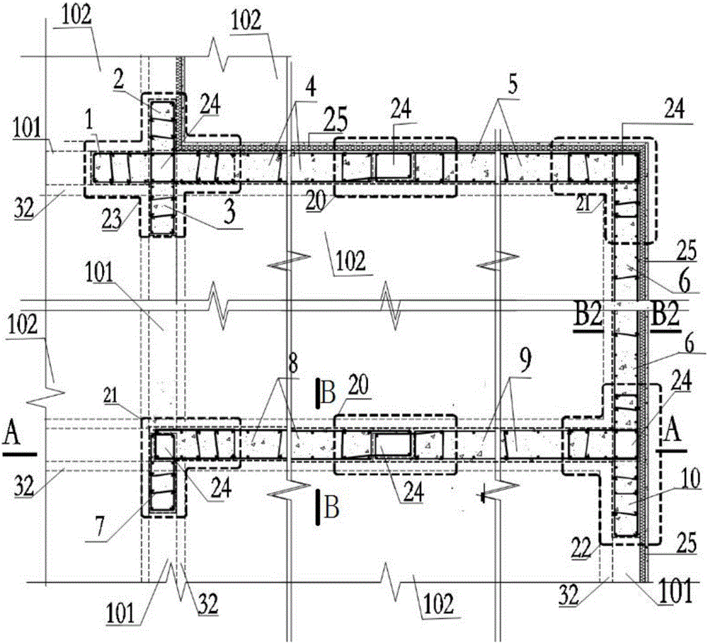
[0116] see figure 1 , a schematic diagram of the implementation of the prefabricated prefabricated structural wall panel unit and its connection nodes of the present invention: there are prefabricated structural wall panel units 1-10, vertical joints 20-23, horizontal slots 32 for horizontal joints to connect nodes, six The vertical through cavity 24; also includes the related connected horizontal members - the prefabricated floor slab 102 and the prefabricated composite beam 101.

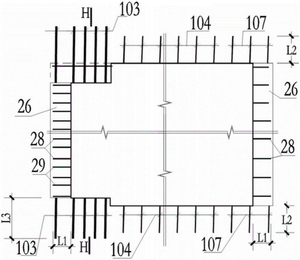
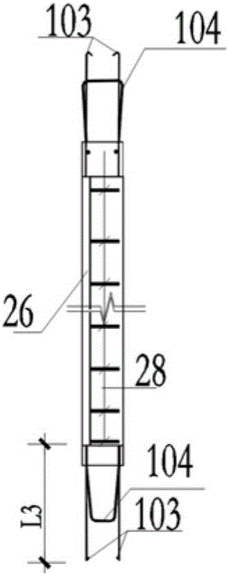
[0117] see Figure 2-8 , the figure starts with figure 1 The prefabricated structural wall panel unit 8 is drawn as a case, and the prefabricated structural wall panel unit is an ordinary prefabricated shear wall, which is a prefabricated member with two surfaces, four joint surfaces and conc...


PUM


Abstract

The invention discloses an assembly type prefabricated structure wallboard unit and connecting joints thereof. The assembly type prefabricated structure wallboard unit is a prefabricated component which is provided with two surfaces and four junction faces and mainly made of concrete. The assembly type prefabricated structure wallboard unit comprises reserved connecting rebars exposed out of the four junction faces. The exposed parts of the reserved connecting rebars on the two vertical junction faces are in a [ shape or an L shape and form the vertical junction face reserved rebars. The reserved connecting rebars comprise the edge component reserved connecting rebars and non-edge component reserved connecting rebars between the junction face at the upper end and the junction face at the lower end, and exposed parts of the rebars form the upper and lower end reserved rebars. The connecting joints comprise the vertical seam connecting joint and the horizontal seam connecting joint. The wallboard unit and the connecting joints have the advantages that site construction is convenient, safety and reliability are achieved, and the wallboard unit and the connecting joints have the same performance of a cast-in-place structure, and the structure design principle that the bearing force of the joints is higher than that of the components is achieved.

Description

technical field [0001] The invention relates to a prefabricated concrete structure, in particular to a prefabricated structural wall panel unit in a prefabricated prefabricated structural wall panel building and a connecting node for connecting the prefabricated structural wall panel units into a whole. Background technique [0002] As a structural form that conforms to the industrialized production method, the fabricated concrete structure has the advantages of fast construction speed, low labor intensity, less noise pollution and wet work, and easy product quality control. The use of prefabricated building construction can effectively save resources and energy, improve the utilization rate of materials in achieving building energy saving and structural performance, reduce the number of on-site construction labor, reduce construction waste and reduce the adverse impact of construction on the environment, improve the overall quality of the building and performance. It can b...

Claims


Application Information

Patent Timeline
IPC IPC(8): E04B1/04E04B2/00E04B1/41E04B1/61
CPCE04B1/043E04B1/41E04B1/61E04B2/00E04B2001/4192
Inventor 刘祥锦刘俊彦
Owner 刘祥锦
Learn More