Pressure-control drilling system utilizing automatic shunt manifold for pressure-control drilling and pressure-control drilling method

It is a technology of managed pressure drilling and automatic flow diversion, which is applied in wellbore/well components, earthwork drilling, flushing wellbore, etc. It can solve the problems of occupying, increasing the cost of wellhead back pressure pump and its ancillary equipment, large site space, etc.

Active Publication Date: 2017-02-15
BC P INC CHINA NAT PETROLEUM CORP +1
View PDF8 Cites 8 Cited by
  • Summary
  • Abstract
  • Description
  • Claims
  • Application Information

AI Technical Summary

Problems solved by technology

However, the disadvantage of this method of applying wellhead back pressure is that the method of applying wellhead back pressure with a back pressure pump increases the cost of the well head back pressure pump and its ancillary equipment, which not only increases the operating cost of managed pressure drilling, but also occupies Since the wellhead back pressure pump system is difficult to maintain on site, once a failure occurs, the managed pressure drilling operation cannot be implemented

Method used


Image

  • Pressure-control drilling system utilizing automatic shunt manifold for pressure-control drilling and pressure-control drilling method
  • Pressure-control drilling system utilizing automatic shunt manifold for pressure-control drilling and pressure-control drilling method

Examples


Embodiment Construction

[0021] The present invention will be further described below in conjunction with the accompanying drawings and specific embodiments, but the following embodiments in no way limit the present invention.

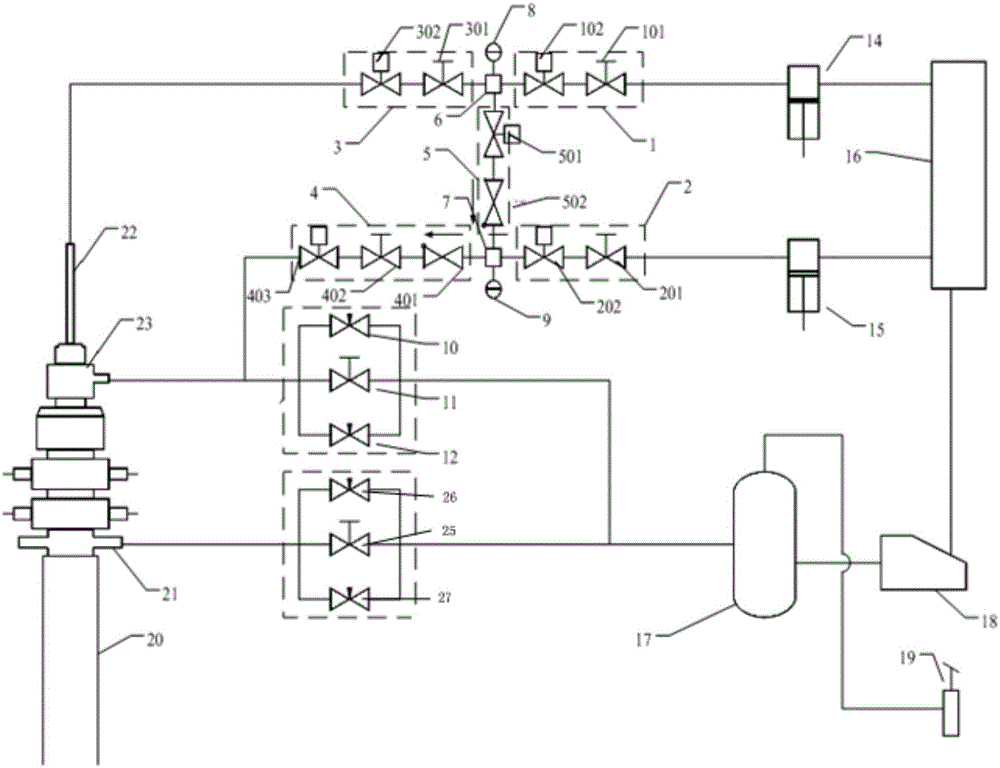
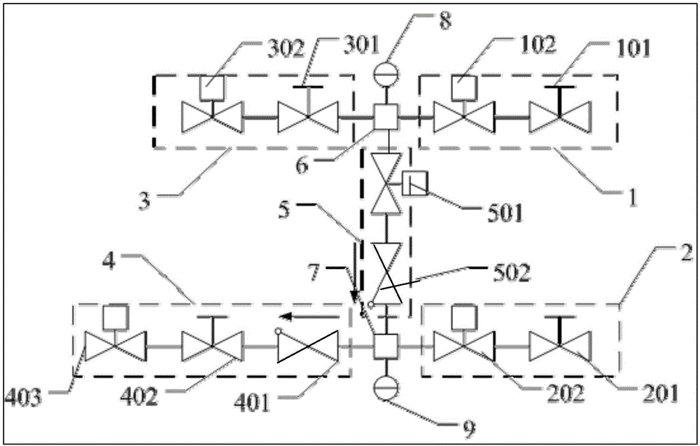
[0022] Such as Figure 1~2 As shown, the managed pressure drilling system includes a drilling spool 21 arranged at the upper wellhead of the wellbore 20, a rotary control head 23 and a drill string 22, and bypass pipes connected to the drill string 22 and the rotary control head 23 respectively. The automatic diverter manifold, the automatic throttling manifold and the throttling manifold that communicate with the bypass pipeline in the blowout direction of the drilling spool 21; specifically,

[0023] The automatic distribution manifold includes a first inflow path 1, a second inflow path 2, a first outflow path 3, a second outflow path 4 and a conversion path 5; the first inflow path 1, the The first outflow path 3 and the conversion path 5 are respectively connected with t...


PUM


Abstract

The invention discloses a pressure-control drilling system utilizing an automatic shunt manifold for pressure-control drilling and a corresponding pressure-control drilling method. The pressure-control drilling system comprises a drilling spool, a rotary control head, a drilling column, an automatic shunt manifold, an automatic throttle manifold and a throttle manifold; the drilling spool, the rotary control head and the drilling column are arranged at a wellhead at the upper part of a mineshaft; and the automatic shunt manifold, the automatic throttle manifold and the throttle manifold respectively communicate with the drilling column, a by-pass pipeline of the rotary control head and a by-pass pipeline in the blowout direction of the drilling spool. Due to the arrangement ways of all the manifolds and the mutual opening/closing matching between hydromatic valves and check valves arranged on all the manifolds and the utilization of a drilling fluid pump equipped for a drilling crew at present, the pressure-control drilling operation is realized; and through controlling the automatic shunt manifold for pressure-control drilling in connection making and tripping processes, the fluctuation of bottom hole pressure can be reduced, the control capacity for the bottom hole pressure can be improved, the no-drilling time can be shortened, the drilling cost can be reduced, and the operation incapability caused by a fault of a pressure return pump can be avoided.

Description

technical field [0001] The invention relates to the technical field of pressure-management drilling, in particular to a pressure-management drilling system and a pressure-management drilling method utilizing the pressure-management drilling automatic diversion manifold. Background technique [0002] During drilling in complex formations, conventional drilling techniques are difficult to solve problems such as overflow, lost circulation, pipe sticking, and well wall collapse caused by narrow density windows, which prolong non-drilling time, increase drilling costs, and even threaten the safety of drilling operations. The managed pressure drilling technology can effectively solve technical problems such as overflow in narrow density windows, lost circulation, stuck pipe, and wellbore collapse during drilling in complex formations. [0003] The control goal of MPD is to keep the bottom hole pressure within the set pressure range by presetting the annular pressure; Comprehensiv...

Claims


Application Information

Patent Timeline
Patent Type & Authority Applications(China)
IPC IPC(8): E21B21/08
CPCE21B21/08
Inventor 郗凤亮马金山齐金涛徐朝阳徐海朝刘刚魏臣兴陈国栋郑燕阳郭云鹏李伟华
Owner BC P INC CHINA NAT PETROLEUM CORP
Why Eureka
Try Eureka