Hydrogen Valve with Leaked Hydrogen Removal

A technology of hydrogen and valves, applied in the direction of valve devices, valve details, gas treatment, etc., can solve the problems of gas removal, no leakage of hydrogen valve packing, complex system, etc., to achieve efficient removal, efficient hydrogen oxidation elimination, safety and The effect of high reliability

Active Publication Date: 2018-09-18
EAST CHINA UNIV OF SCI & TECH
View PDF11 Cites 1 Cited by
  • Summary
  • Abstract
  • Description
  • Claims
  • Application Information

AI Technical Summary

Problems solved by technology

However, the catalytic reaction device needs to install a precise temperature control heating system, and the system is relatively complicated.
[0008] At present, there is no relevant device and method for removing gas leakage from the hydrogen valve packing.

Method used


Image

  • Hydrogen Valve with Leaked Hydrogen Removal
  • Hydrogen Valve with Leaked Hydrogen Removal
  • Hydrogen Valve with Leaked Hydrogen Removal

Examples


Embodiment 1

[0043] Embodiment 1, a hydrogen valve with leaking hydrogen removal function, such as Figure 1-8 As shown, it includes: a valve body 6, packing 7, packing gland 5, valve stem 4 and a hydrogen absorption reactor arranged on the packing gland 5, wherein the valve body 6 is provided with an opening, and the valve stem 4 is arranged on the In the above opening, the bottom of the valve stem is connected with the valve core to control the on-off state of the valve, the upper end of the valve stem is drawn out from the opening, and the space between the lower end of the valve stem and the inner wall of the opening is filled with filler 7 to play the role of the valve. The leading end of the stem is airtightly connected with the inside of the valve to prevent hydrogen leakage in the valve; the packing gland 5 is set in a cylindrical structure and is sleeved on the valve stem 4. Specifically, the packing gland 5 shaft A through hole 53 is opened in the center, the valve stem passes th...

Embodiment 2

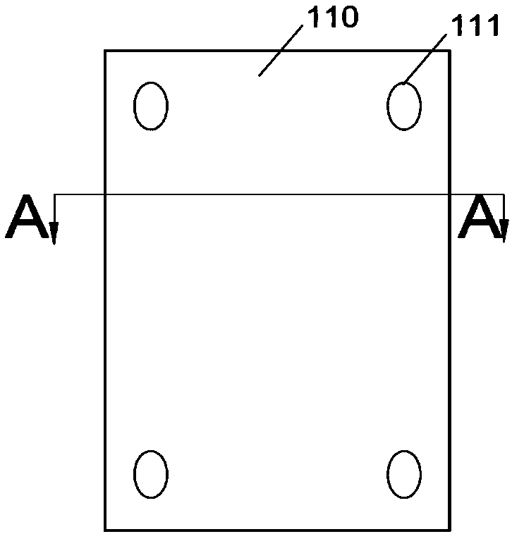
[0045] Embodiment 2, the upper end of the packing gland is provided with a protrusion, and the upper end of the packing gland is fixed on the valve body 6 at the upper end of the opening through the first bolt 1, and the upper end of the first bolt 1 is connected to the protrusion through a nut 8. The metal plate of the hydrogen absorption reactor is provided with several threaded holes 111 for installation, and the inner wall of the groove is provided with threaded holes, and the hydrogen absorption reactor is fixed in the groove by the second bolt 3, The hydrogen absorption reactor does not protrude from the groove. The packing gland and the opening of the valve body are in clearance fit, and the difference between the outer diameter of the packing gland and the inner diameter of the opening is 0.5 mm to 1 mm, and the outer hydrogen absorption reactor is exposed in this gap; the packing gland and the valve stem are in clearance fit, The difference between the inner diameter ...

Embodiment 3

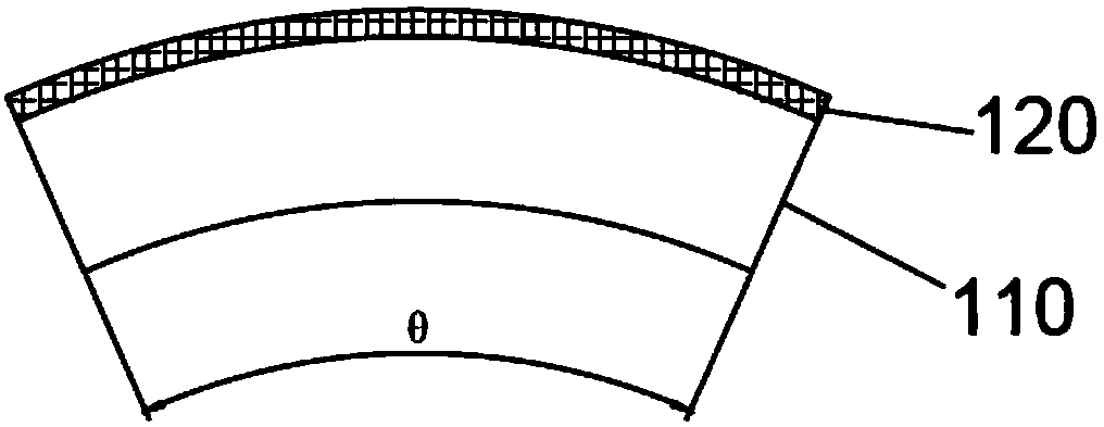
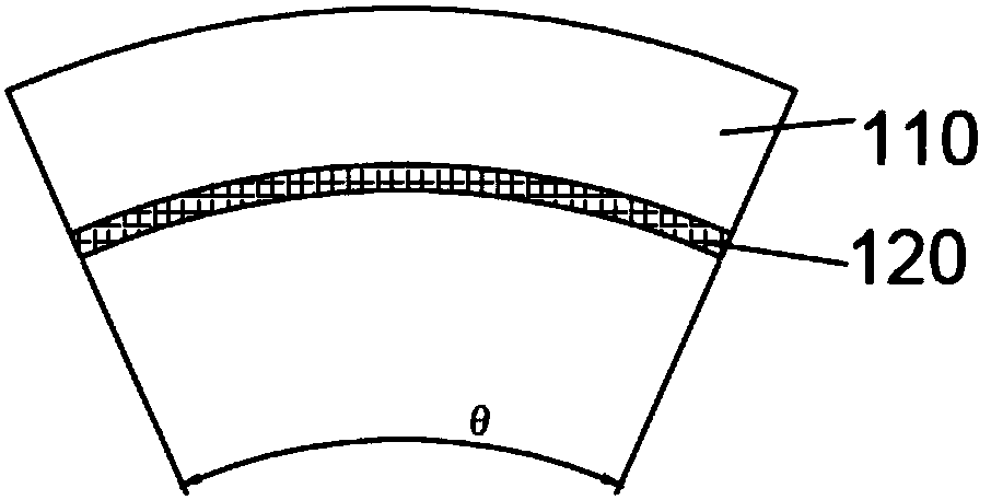
[0046] Embodiment three, such as Figure 1-3 As shown, the hydrogen absorption reactor specifically includes a metal plate 110 and a catalyst coating 120 coated on the surface of the metal plate, wherein the thickness of the metal plate is 0.4mm, and the metal plate is made of a sandblasted iron-chromium-aluminum metal plate , the aluminum content is 5wt%; Catalyst coating 120, it is evenly coated on the surface of described metal plate, and described catalyst coating is made of hydrophobic Pd / Pt-Al 2 o 3 made, coated with Pd / Pt-Al 2 o 3 Hydrophobic catalyst-coated iron-chromium-aluminum metal plates form a hydrogen absorption reactor. The catalyst coating can catalyze the removal of hydrogen leaked from the valve packing at room temperature. The activity is specific, to achieve continuous and stable removal of leaked hydrogen, and to improve the safety of hydrogen valves. In this embodiment, for the convenience of installation, the metal plate is set as a circular arc pan...


PUM

PropertyMeasurementUnit
thicknessaaaaaaaaaa
thicknessaaaaaaaaaa
angleaaaaaaaaaa

Abstract

The invention discloses a hydrogen valve with a function of removing leaked hydrogen. The valve comprises a valve body, a valve rod, padding and a padding gland. A plurality of first grooves are symmetrically formed in the outer wall of the padding gland in the circumferential direction, a plurality of second grooves are correspondingly formed in the inner wall of the padding gland in the circumferential direction, and the first grooves and the second grooves are internally provided with hydrogen absorbing reactors. The hydrogen absorbing rectors are provided with Pd / Pt-Al2O3 catalyst coatings and located in an opening in the upper end of the padding, and the catalyst coatings are exposed in the grooves. An iron, chromium and aluminum metal plate is coated with the hydrophobic Pd / Pt-Al2O3 catalyst coatings and installed in the grooves formed in the inner wall face and the outer wall face of the padding gland, and efficient hydrogen oxidation removing is achieved at the normal temperature. Meanwhile, by means of the character of the Pd / Pt-Al2O3 catalyst coatings, effective draining of reaction product water is achieved, and stability of the catalysts is guaranteed. The valve has the beneficial effects of being simple and safe in structure and capable of efficiently removing leaked hydrogen.

Description

technical field [0001] The invention relates to the technical field of leakage gas treatment. More specifically, the invention relates to a hydrogen valve with a function of removing hydrogen leakage. Background technique [0002] Valves are an indispensable part of industrial installations, and many of them are used in highly corrosive, toxic or flammable and explosive working conditions. The global industrial valve market is about 35 billion US dollars, of which China's industrial valve consumption accounts for about 25% of the global industrial valve output. As a general-purpose machine with pressure and flow, the valve is an important research topic to reduce the leakage of its medium and avoid the damage of leakage to safety and environment. [0003] Valve leakage is divided into two categories, namely external leakage and internal leakage. No matter what kind of leakage is, it may cause loss of medium and environmental pollution, and even cause fire, explosion, poison...

Claims


Application Information

Patent Timeline
Patent Type & Authority Patents(China)
IPC IPC(8): F16K41/02B01D53/86B01D53/46
CPCB01D53/8671B01D2255/1021B01D2255/1023B01D2255/2092B01D2257/108F16K41/02
Inventor 于新海张健杨留于伟涂善东
Owner EAST CHINA UNIV OF SCI & TECH
Why Eureka
Try Eureka