Cladding power stripper for removing high-order mode laser and manufacturing method of cladding power stripper

A high-order mode and stripper technology, which is applied to lasers, laser parts, laser parts, etc., can solve the problems of weakening device performance, incomplete pump light stripping, and insufficient high-order mode laser effusion. Improve the ability to be stripped, ensure safe and normal operation, and improve the effect of beam quality

Active Publication Date: 2017-02-15
WUHAN RAYCUS FIBER LASER TECHNOLOGY CO LTD
View PDF6 Cites 17 Cited by
  • Summary
  • Abstract
  • Description
  • Claims
  • Application Information

AI Technical Summary

Problems solved by technology

[0004] At present, the most commonly used method of stripping the cladding light is to coat the surface of the cladding with a high-refractive-index UV-curable glue. In high-power fiber lasers, the power of the cladding light is relatively large, and the glue has a strong polymer as a polymer. Light-absorbing properties will cause the temperature of the glue-coated area to be too high, resulting in a serious weakening of device performance
The other is to roughen the surface of the inner cladding by mechanical and chemical methods, so that the cladding light cannot meet the requirements of total reflection and leak out.
However, the above methods all have the problems of incomplete pump light stripping and insufficient high-order mode laser bleeding.

Method used


Image

  • Cladding power stripper for removing high-order mode laser and manufacturing method of cladding power stripper
  • Cladding power stripper for removing high-order mode laser and manufacturing method of cladding power stripper
  • Cladding power stripper for removing high-order mode laser and manufacturing method of cladding power stripper

Examples


Embodiment 1

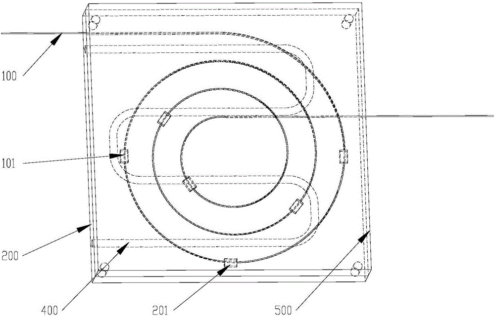
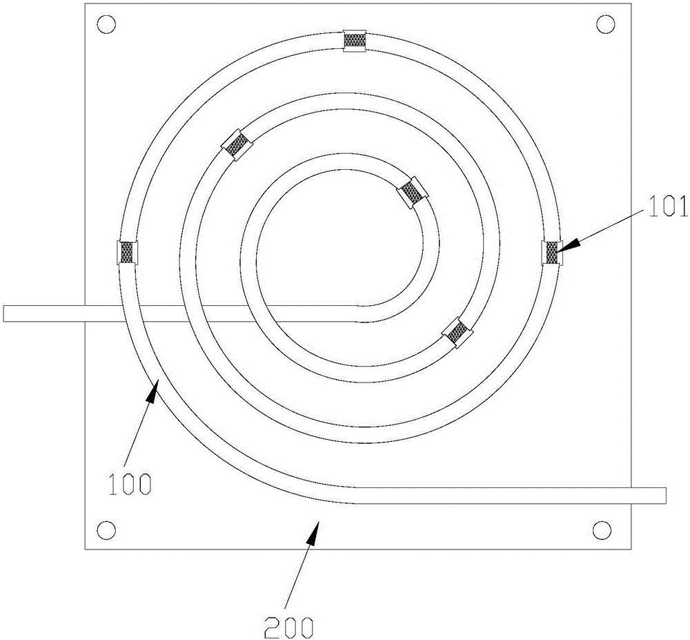
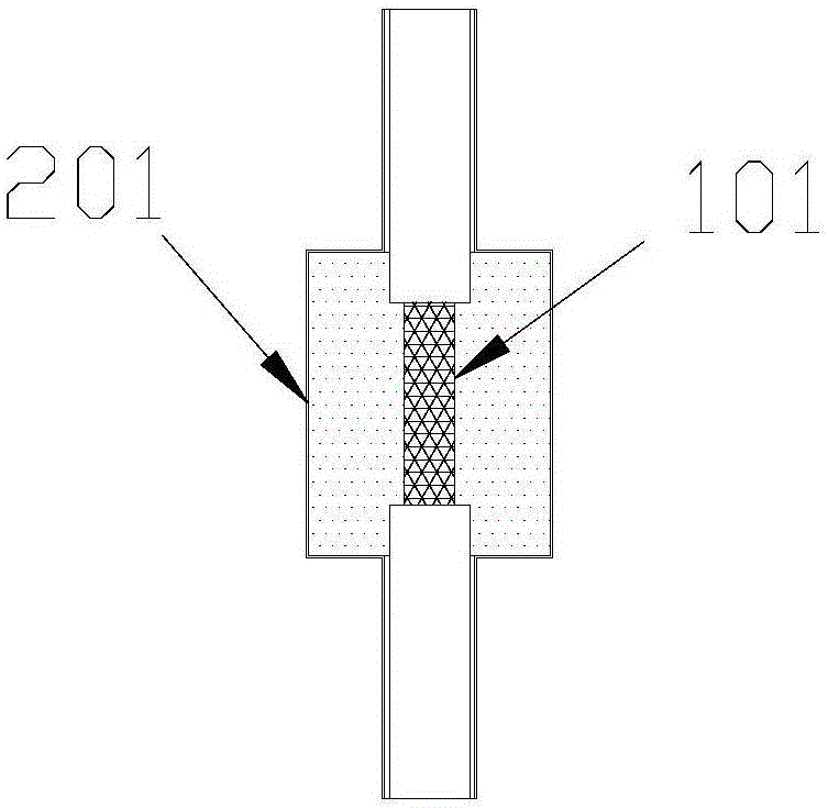
[0029] The annular water-cooling channel 400 is coiled in the annular groove of the heat sink 200, and a section of optical fiber of a specified length is cut off, coiled in the annular groove of the heat sink 200, and the optical fiber section suspended on the heat sink groove 201 is marked, and used The wire stripper strips off the coating layer of the optical fiber at the marked place, and the stripped length of the coating layer is slightly smaller than the length of the heat sink groove 201; the bare fiber with the coating layer stripped off is mechanically processed to form an optical fiber etching section 101, so that the surface Irregular V-groove morphology is formed; then the processed optical fiber is cleaned in an ultrasonic cleaning machine equipped with clean ethanol, and the surface solvent is dried with an air compression gun. The cleaned optical fiber is coiled on the heat sink 200 again, and the optical fiber etching section 101 is suspended in the center of t...

Embodiment 2

[0031] The structure of this embodiment is the same as that of Embodiment 1, except that the heat conduction medium 300 in the heat sink groove 201 is silicon carbide, and the housing cover plate 500 is made of nickel-plated brass.


PUM


Abstract

The present invention relates to a cladding power stripper for removing high-order mode laser and a manufacturing method of the cladding power stripper. The cladding power stripper is structured in the following manners that: an optical fiber is coiled in an annular groove of a heat sink; an annular water cooling channel is coiled in the annular groove of the heat sink; a plurality of heat sink recessed grooves are arranged in the annular groove of the heat sink; the surfaces of optical fiber segments suspended on the heat sink recessed grooves are etched so as to form irregular V-shaped groove structures; and the heat sink recessed grooves are filled with a heat-conducting medium; the heat conducting medium completely coats the etched optical fiber segments; and a shell cover plate enables encapsulation protection for the heat sink. According to the cladding power stripper of the present invention, the coating layer of the double-cladding optical fiber is stripped off at intervals, and an exposed inner cladding layer is mechanically etched into the irregular V-shaped grooves so as to be adopted as the dipping openings of cladding light; leaked cladding power is absorbed by the heat conducting medium; heat is transferred to the heat sink and then is taken away by cooling water; the optical fiber is bent into an annular shape, so that the stripping efficiency of high-order mode cladding light can be increased, and light beam quality can be improved.

Description

technical field [0001] The invention belongs to the field of high-power fiber lasers, and in particular relates to a cladding power stripper for removing high-order mode-stripping lasers and a manufacturing method. [0002] technical background [0003] Fiber lasers are widely used in metal cutting, welding, marking, material processing, and national defense security due to their characteristics of good beam quality, low power consumption, small size, and long life. In particular, the output power of high-power fiber lasers has been increasing year by year, and the maximum single-mode output has exceeded 10,000 watts. In high-power lasers and amplifiers, double-clad doped fibers are used as active fibers, and the pump light is coupled into the fiber core by cladding pumping. Due to the problem of absorption rate, there will always be some residual pump light in the cladding; at the same time, there is inevitably a fusion point in the fiber laser, and part of the core light w...

Claims


Application Information

Patent Timeline
Patent Type & Authority Applications(China)
IPC IPC(8): G02B6/245G02B6/036H01S3/067H01S3/094H01S3/04
CPCG02B6/245G02B6/03694H01S3/0407H01S3/06704H01S3/094007
Inventor 骆崛逵
Owner WUHAN RAYCUS FIBER LASER TECHNOLOGY CO LTD
Why Eureka
Try Eureka