Negative entity modeling method

A modeling method and solid technology, applied in simulators, instruments, computer control, etc., can solve problems such as poor readability, theoretical errors between the design digital model and actual parts, and low client computing efficiency, so as to reduce difficulty and work. volume, improve consistency

Inactive Publication Date: 2017-02-15
SHENYANG AIRCRAFT DESIGN INST AVIATION IND CORP OF CHINA
View PDF4 Cites 0 Cited by
  • Summary
  • Abstract
  • Description
  • Claims
  • Application Information

AI Technical Summary

Problems solved by technology

[0003] 1) The modeling process of designing digital models has poor readability, which is not conducive to digital model maintenance, and the client operation efficiency is low when the design digital model modeling process is complicated;
[0004] 2) It is difficult to classify the same kind of tools for parts, which leads to frequent tool changes during processing;
[0005] 2) The utilization rate of the process digital model in the programming process to the design digital model is extremely low, and even the process digital model of most parts has to be rebuilt;
[0006] 3) There are a large number of phenomena that the rounding and chamfering of the design digital model cannot be processed by CNC;
[0007] 4) The closed-angle processing part cannot construct geometric features in the design digital model, resulting in a theoretical error between the design digital model and the actual part, causing certain difficulties to the inspection work

Method used


Image

  • Negative entity modeling method

Examples


Embodiment Construction

[0027] In order to make the objectives, technical solutions and advantages of the present invention clearer, the technical solutions in the embodiments of the present invention will be described in more detail below in conjunction with the drawings in the embodiments of the present invention. In the drawings, the same or similar reference numerals denote the same or similar elements or elements having the same or similar functions throughout. The described embodiments are some, but not all, embodiments of the invention. The embodiments described below by referring to the figures are exemplary and are intended to explain the present invention and should not be construed as limiting the present invention. Based on the embodiments of the present invention, all other embodiments obtained by persons of ordinary skill in the art without creative efforts fall within the protection scope of the present invention. Embodiments of the present invention will be described in detail below ...


PUM


Abstract

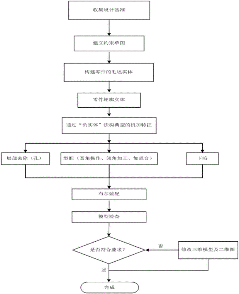
The invention discloses a negative entity modeling method, and belongs to the technical field of machining modeling. According to the negative entity method, a modeling sequence of negative entities is determined according to the processing sequence, parts which are cut in one step by cutters of the same specification in the processing process are simulated via negative entities, and the negative entities represents parts that needs to be removed from a processing entity. The method comprises the following steps that 1) a design reference is collected, and a constraint sketch of a part to be established is drawn; 2) a blank entity of the part to be established is established according to the constraint sketch; 3) a contour entity of the part to be established is established; 4) a negative entity packet is established according to the processing sequence; 5) a geometric parameter feature of the part to be established is processed according to the negative entity packet; and 6) the established contour entity is inspected. According to the invention, the modeling process is standard, the design quality and working efficiency are improved, manufacture related work is considered in the design stage, and the consistency between a design digital model and a technical digital model is improved.

Description

technical field [0001] The invention belongs to the technical field of machining modeling, and in particular relates to a negative solid method modeling method. Background technique [0002] Most of the metal machined parts on the aircraft are processed by CNC, and these parts have complex shapes and high processing precision requirements, especially very important large parts, such as frames, beams and other load-bearing components, which are difficult to process. Most of the frame and beam parts are curved surfaces with lug joints. In order to meet a series of requirements such as strength, structural layout, and weight, multiple cavities will be designed inside the machined parts (generally, the removal of the "cavity" inside the part is called a cavity), which also includes partial closed angles. Processing, which in turn increases the difficulty of CNC machining. The traditional CATIA modeling conforms to the design intent with the final geometric features, but cannot...

Claims


Application Information

Patent Timeline
IPC IPC(8): G05B19/4097
CPCG05B19/4097G05B2219/32339
Inventor 张明
Owner SHENYANG AIRCRAFT DESIGN INST AVIATION IND CORP OF CHINA
Why Eureka
Try Eureka