High-voltage and large-current plug and high-voltage and large-current connector
A high-current connector and plug-in technology, applied in the direction of electrical component connection, conductive connection, connection, etc., can solve the problems of increasing the contact resistance of male and female conductors, increasing the safety hazard of new energy vehicle fires, etc. The effect of sealing performance
- Summary
- Abstract
- Description
- Claims
- Application Information
AI Technical Summary
Problems solved by technology
Method used
Image
Examples
Embodiment 1
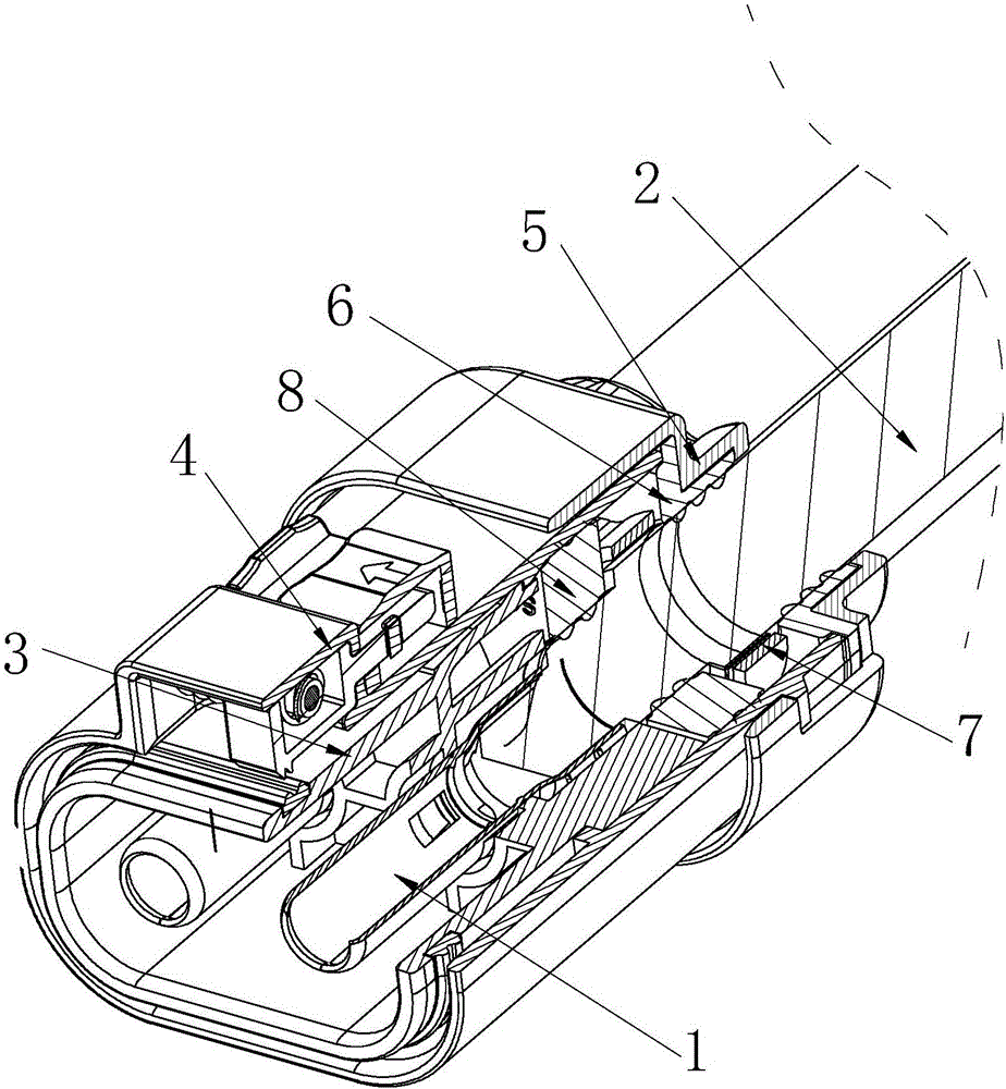
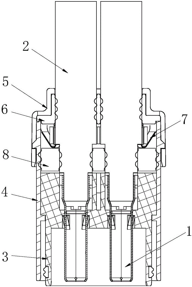
[0034] figure 1 It is a partially cut-away perspective view of Embodiment 1 of the present invention, figure 2 It is a sectional view of Embodiment 1 of the present invention. In the figure, the meanings of each reference mark are as follows: 1. Plug pin; 2. Shunt cable; 3. Plug rubber core; 4. Plug shell; 5. Plug tail cover; 6. Waterproof pad at the tail of the plug; 7 , Plug shielding contact piece; 8, The waterproof ring armor inside the plug.
[0035] A high-voltage and high-current plug, including two plug male pins 1, the plug male pin 1 is sleeve-shaped, the tail of the plug male pin 1 is used to be inserted by the shunt cable 2, and the middle part of the plug male pin 1 is embedded In the plug rubber core 3, the head of the male pin 1 of the plug is used to be detachably inserted into the outlet distribution base contact piece 10 of the socket, and the socket distribution base contact piece 10 is embedded in the socket distribution base 9, and the plug glue Core 3...
Embodiment 2
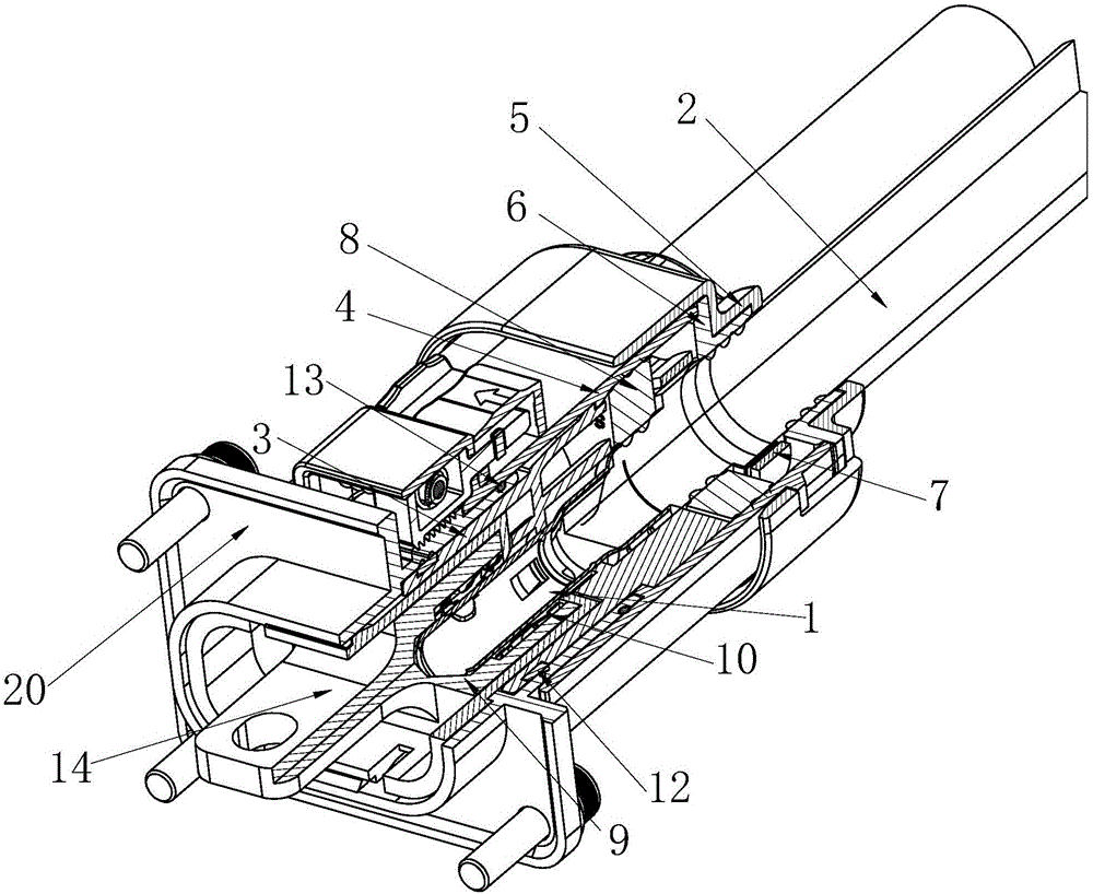
[0044] image 3 It is a partially cut-away perspective view of Embodiment 2 of the present invention, Figure 4 It is a sectional view of Embodiment 2 of the present invention, Figure 5 It is a partially cut-away perspective view of the socket in Embodiment 2 of the present invention; Figure 6 is an exploded view of the connection of conductive members in Example 2. In the figure, the same reference numerals as those used in the above-mentioned embodiments still use the definition of the reference numerals in the above-mentioned embodiments, and the meanings of the newly appearing reference numerals in the figure are as follows: 9. The socket shunt base; 10 1. Socket shunt matrix contact sheet; 11. Socket rubber core; 12. Plug internal waterproof ring B; 13. Socket shell waterproof ring; 14. Copper bar connecting plate; 15. Copper bar connecting hole; 20. Socket shell.
[0045] A high-voltage and high-current connector, including a socket and any of the above-mentioned hi...
Embodiment 3
[0058] Figure 7 It is a partially cutaway perspective view of Embodiment 3 of the present invention, Figure 8 It is a sectional view of Embodiment 3 of the present invention, Figure 9 It is a partially cut-away perspective view of the socket in Embodiment 3 of the present invention; Figure 10 is an exploded view of the conductive member connection in Example 3. In the figure of this embodiment, the same reference numerals as those used in the above-mentioned embodiments still use the definition of the reference numerals in the above-mentioned embodiment, and the meanings of the newly appearing reference numerals in the figure are as follows: 16. Connecting ears plate; 17, threaded hole; 18, copper row connecting rod; 19, copper row connecting rod meson.
[0059] The difference between this embodiment and the above-mentioned embodiments is that the socket is an elbow socket, and the socket diverter base 9 is provided with a connecting lug 16 extending along the axis of t...
PUM
 Abstract
Description
Claims
Application Information
 - R&D
- Intellectual Property
- Life Sciences
- Materials
- Tech Scout
- Unparalleled Data Quality
- Higher Quality Content
- 60% Fewer Hallucinations
Browse by: Latest US Patents, China's latest patents, Technical Efficacy Thesaurus, Application Domain, Technology Topic, Popular Technical Reports.
© 2025 PatSnap. All rights reserved.Legal|Privacy policy|Modern Slavery Act Transparency Statement|Sitemap|About US| Contact US: help@patsnap.com


