Structure for freely adjusting direction of optical axis of laser

A technology of optical axis direction and laser, which is applied in the field of engineering measurement, can solve the problems of time-consuming and labor-intensive installation and adjustment, difficulty in realizing fast installation requirements, complicated mechanism, etc., and achieve good elastic effect

Inactive Publication Date: 2017-02-15
BEIJING AEROSPACE INST FOR METROLOGY & MEASUREMENT TECH +1
View PDF8 Cites 1 Cited by
  • Summary
  • Abstract
  • Description
  • Claims
  • Application Information

AI Technical Summary

Problems solved by technology

[0003] At present, there is no fixed angle relationship between the shell and the optical axis of commonly used lasers. After installing the laser according to the size of the shell, it is necessary to make precise pointing adjustments to the outgoing optical axis of the laser. At present, the common method is to use the repair and research installation base The precise pointing of the optical axis can be achieved by using the surface method, but the installation and adjustment of this method is time-consuming and laborious, and it is difficult to realize the occasions requiring fast installation.
In addition, a two-dimensional orthogonal rotation mechanism is designed to realize the adjustment of the optical axis pointing. This method has the disadvantages of complex mechanism and large volume.

Method used


Image

  • Structure for freely adjusting direction of optical axis of laser

Examples


Embodiment Construction

[0014] The present invention will be described in further detail below in conjunction with the accompanying drawings and embodiments.

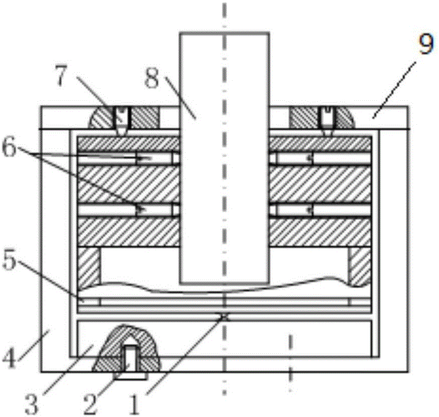
[0015] A mechanism for free adjustment of the optical axis direction of a laser, including a base 4, a flexible hinge structure 3, an upper cover 9, and 4 adjustment screws 7 that are perpendicular to each other through the center of the adjustment mechanism, and the flexible hinge structure 3 is installed The screw 2 is fixed inside the base 4; the upper end of the base 4 is fixed by the upper cover 9 screws; the laser 8 is fixed in the round hole in the center of the flexible hinge 3 through the laser fixing screw 6; the adjustment screw 7 passes through the upper cover 9 to resist the flexible hinge Structure 3 upper part.

[0016] There is a cylindrical hole at the lower end of the center of the flexible hinge structure 3. The radius of the cylindrical hole is larger than the central circular hole where the laser 8 is placed on the upper p...


PUM


Abstract

The invention relates to the technical field of engineering measurement and more particularly to a structure for freely adjusting the direction of the optical axis of a laser. The adjusting mechanism comprises a base, a flexible hinge structure, an upper cover, and a plurality of adjusting screws. The flexible hinge structure is fixed inside the base; the upper end of the base is fixed to the upper cover; the laser is fixed in a circular hole in the center of the flexible hinge; the adjusting screws pass through the upper cover to be abutted against the upper part of the flexible hinge structure. The laser is a semiconductor laser with a diameter of 20mm and a wavelength of 650nm. The base material is 6061-T6 aluminum alloy. The flexible hinge is made of spring steel material and quenched, and has good flexibility. The semiconductor laser is fixed to the flexible adjustment mechanism by being locked in the radial direction by locking screws, and the precision adjustment of the laser optical axis can be realized by adjusting the four adjusting screws arranged orthogonally on the upper end face of the base in the hinge direction.

Description

technical field [0001] The invention belongs to the technical field of engineering measurement, and in particular relates to a structure for free adjustment of the optical axis direction of a laser. Background technique [0002] In the field of precision engineering measurement technology such as laser measurement, lasers with high collimation characteristics are often used, and the precise adjustment of the optical axis of the laser is involved. [0003] At present, there is no fixed angle relationship between the shell and the optical axis of commonly used lasers. After installing the laser according to the size of the shell, it is necessary to make precise pointing adjustments to the outgoing optical axis of the laser. At present, the common method is to use the repair and research installation base The precise pointing of the optical axis can be realized by the surface method, but the installation and adjustment of this method is time-consuming and laborious, and it is d...

Claims


Application Information

Patent Timeline
Patent Type & Authority Applications(China)
IPC IPC(8): H01S5/022H01S5/02
Inventor 宋金城刘柯孙增玉高越董利军缪寅宵郑明珠陈晓晖
Owner BEIJING AEROSPACE INST FOR METROLOGY & MEASUREMENT TECH
Why Eureka
Try Eureka