A portable power supply for permanent magnet vibration power generation

A technology of vibration power generation and portable power supply, applied in battery circuit devices, current collectors, electric vehicles, etc., can solve the problem of not improving the conversion efficiency of mechanical energy, and achieve the effect of increasing the amplitude, improving the conversion rate and reducing the cost.

Inactive Publication Date: 2019-03-22
杨明远
View PDF5 Cites 0 Cited by
  • Summary
  • Abstract
  • Description
  • Claims
  • Application Information

AI Technical Summary

Problems solved by technology

Patent CN1877973A discloses a vibration power generation device for portable electronic equipment. The device adopts a magnetic spring structure. A fixed permanent magnet is installed at both ends of the movement cavity, and a movable permanent magnet with opposite polarity is placed in the movement cavity. Form a magnetic spring structure, the winding group is wound on the outer wall of the moving chamber, and the winding group is a double-winding coil, which is wound on the outer wall of the moving chamber in opposite directions. The characteristics of this coil structure are: the two coils are wound in opposite directions , then the electromotive force in the two coils is also reversed, and the single-phase conductivity of the diode can ensure the unidirectional continuity of the current direction, but it does not affect the conversion efficiency of mechanical energy to electrical energy
That is, the positions of the two coils overlap, but for each coil, there is a problem of mutual cancellation of the electromotive force; The winding directions of the two sets of coils are the same or opposite, which cannot improve the conversion efficiency of mechanical energy to electrical energy

Method used


Image

  • A portable power supply for permanent magnet vibration power generation
  • A portable power supply for permanent magnet vibration power generation
  • A portable power supply for permanent magnet vibration power generation

Examples


Embodiment 1

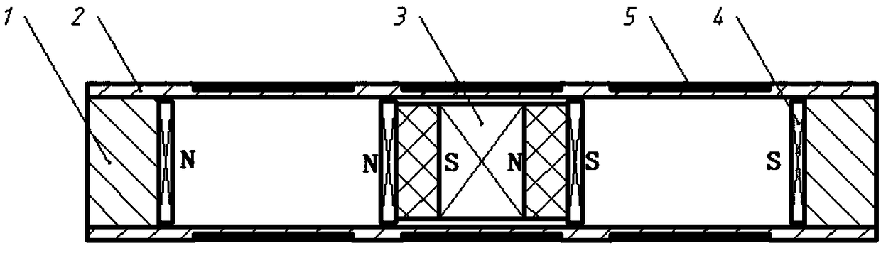
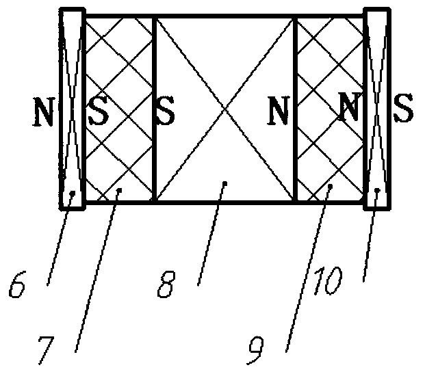
[0037] The permanent magnet vibration power generation portable power supply of this embodiment includes a vibration power generation device and a power electronic conversion circuit part. The vibration power generation device is connected with the power electronic conversion circuit part. The vibration power generation device collects vibration energy and converts it into electrical energy. The power electronic conversion circuit part supplies power to the load; the vibration generating device includes a magnet part, a coil part and a mechanical support part, and the magnet part is composed of two fixed permanent magnets 4 respectively fixed at both ends of the mechanical support part and one placed in the mechanical support part The moving magnet 3 is composed of the moving magnet 3 and the fixed magnet 4 at both ends have a repulsive force, that is, as figure 1 As shown, the N pole of the fixed magnet 4 at the left end is opposite to the N pole of the moving magnet 3, and th...

Embodiment 2

[0042] The permanent magnet vibration power generation portable power supply of this embodiment includes a vibration power generation device and a power electronic conversion circuit part. The vibration power generation device is connected with the power electronic conversion circuit part. The vibration power generation device collects vibration energy and converts it into electrical energy. The power electronic conversion circuit part supplies power to the load; the vibration power generation device includes a magnet part, a coil part and a mechanical support part, and the magnet part is composed of two fixed permanent magnets 4 respectively fixed at both ends of the mechanical support part and one placed in the mechanical support part The moving magnet 3 is composed of the moving magnet 3 and the fixed magnet 4 at both ends have a repulsive force, that is, as figure 1As shown, the N pole of the fixed magnet 4 at the left end is opposite to the N pole of the moving magnet 3, a...

Embodiment 3

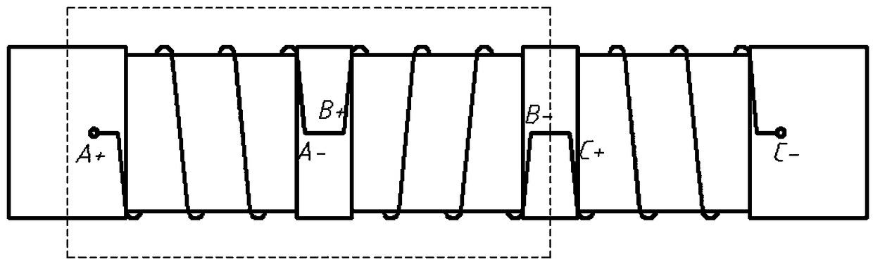
[0046] The composition and connection relationship of the various parts of the permanent magnet vibration power generation portable power supply in this embodiment are the same as in the first embodiment, except that the coil part is wound by the winding method of the second embodiment.


PUM


Abstract

The invention relates to a potable permanent-magnet vibration generation power supply comprising a vibration generation device and a power electronic conversion part. The vibration generation device connected with the power electronic conversion part collects vibration energy and coverts the energy into electric energy; and the generated electric energy as power is provided for a load by the power electronic conversion part. The vibration generation device consists of a magnet part, a coil part and a mechanical support part; the magnet part is formed by two fixed permanent magnets fixed at the two ends of the mechanical support part respectively and a moving magnet arranged inside the mechanical support part, wherein repulsive forces are formed between the moving magnet and the fixed permanent magnets at the two ends; and the coil part winds around the outer wall of the mechanical support part. The power supply is characterized in that the moving magnet includes three permanent magnets and two soft magnets; and the three permanent magnets are arranged in front of the two soft magnets and a repulsion effect is formed between each two adjacent permanent magnets.

Description

technical field [0001] The technical solution of the present invention relates to a device for recovering mechanical vibration energy and converting it into electric energy, in particular to a portable power source for permanent magnet vibration power generation. Background technique [0002] With the development of micro-electro-mechanical systems, low-cost, low-power power supplies used in bridge status detection, environmental monitoring, medical care, and automobile manufacturing have attracted widespread attention. Due to the limitation of battery life and considering the impact of discarded batteries on the environment, researchers have been working on the research of replacing batteries with other power sources, such as solar energy, wind energy, vibration energy, etc. Solar energy and wind energy can only be obtained in places with sufficient sunlight and wind power. When photovoltaic power generation or wind power generation systems are embedded in micro-electromech...

Claims


Application Information

Patent Timeline
Patent Type & Authority Patents(China)
IPC IPC(8): H02K35/02H02J7/32H02M1/32
CPCH02J7/0029H02J7/32H02K35/02H02M1/32Y02B40/00
Inventor 杨明远
Owner 杨明远
Why Eureka
Try Eureka