Supercharge Your Innovation With Domain-Expert AI Agents!

Method for producing a preliminary material for a cutting tool and corresponding preliminary material

A cutting tool, cutting material technology, applied in the direction of manufacturing tools, metal material coating process, other manufacturing equipment/tools, etc., can solve the problem of low processing speed, achieve cost savings, large cost advantages, and improve processing speed. Effect

Active Publication Date: 2017-02-15
フストアルピネプレシジョンストリップゲーエムベーハー
View PDF9 Cites 0 Cited by
  • Summary
  • Abstract
  • Description
  • Claims
  • Application Information

AI Technical Summary

Problems solved by technology

However, the powder metallurgy production of the cutting area has the disadvantage that the achievable processing speeds are lower than in the welding of edge wires

Method used


Image

  • Method for producing a preliminary material for a cutting tool and corresponding preliminary material
  • Method for producing a preliminary material for a cutting tool and corresponding preliminary material
  • Method for producing a preliminary material for a cutting tool and corresponding preliminary material

Examples


Embodiment Construction

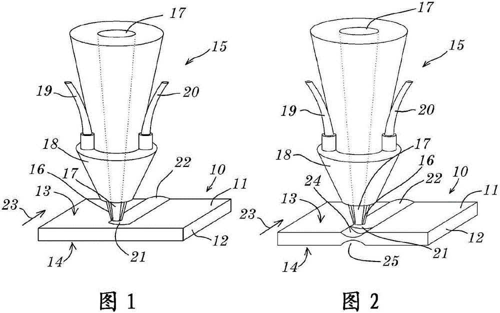
[0055] FIG. 1 shows schematically a first embodiment of the method according to the invention for producing a roughing material for a cutting tool, in particular for producing a saw blade, a saw band or a cutting wire. A flat carrier 10 can be seen, which in the example shown comprises only a uniform base body 11 of carrier material. In the example shown, the flat carrier is shown as a short section for better clarity. However, it is preferably a continuous web which is unwound, for example, from a reel which is not shown here. The flat carrier 10 has a front side 13 and a rear side 14 , which are flat in the example shown. A first particulate cutting material 16 is applied to the front side 13 of the flat carrier 10 by means of a welding head 15 of a welding device (not further shown) and melted by means of a laser beam 17 so that the carrier 10 and the particulate cutting material 16 capable of being welded to each other. In the example shown, the welding head 15 of the w...


PUM


Abstract

The invention relates to a method for producing a preliminary material for a cutting tool, in particular a preliminary material for a saw blade, a saw band, a cutting line, a punching knife, or a blade, wherein at least one first particulate cutting-edge material (16, 16a) is applied to a planar carrier (10), the first particulate cutting-edge material (16) is welded to the planar carrier (10), and the planar carrier (10) is separated substantially along the weld joint (22, 27) thus produced. The invention further relates to a corresponding planar preliminary material.

Description

technical field [0001] The invention relates to a method for the production of a roughing material for cutting tools, in particular as a roughing material for the production of saw blades, saw bands, cutting wires, punching knives or blades, such as scraper blades . The invention also relates to a corresponding roughing material. Background technique [0002] Cutting tools such as band saws for metalworking must meet a whole series of requirements in order to be used economically: the strip must be flexible and elastic, it must not only absorb and withstand tensile stresses, the saw band starts with its mounting This tensile stress is already withstood, and in addition it must be able to withstand the forces required for bending of the strip during sawing and the corresponding torsional moments and torsional stresses when the strip is rotated about its longitudinal axis above and below the cutting table or in front of and behind the cutting position , the belt bears the to...

Claims


Application Information

Patent Timeline
IPC IPC(8): B23D65/00
CPCB23D65/00B23K2101/20B23K31/02B23P15/28C23C26/00B23K31/022
Inventor L·阿荷内尔G·迈尔霍费尔M·内斯瓦德巴
Owner フストアルピネプレシジョンストリップゲーエムベーハー
Features
  • R&D
  • Intellectual Property
  • Life Sciences
  • Materials
  • Tech Scout
  • Unparalleled Data Quality
  • Higher Quality Content
  • 60% Fewer Hallucinations
Learn More