
Simulation mechanical arm type medical magnifying glass system

A technology of a robotic arm and a magnifying glass, which is applied in the field of a simulated robotic arm medical magnifying glass system, can solve the problems of users' visual fatigue, difficulty in picking and wearing, and easy fatigue, and achieves the effect of improving accuracy and reducing visual fatigue.

Inactive Publication Date: 2017-02-22
重庆金创谷医疗科技有限公司
View PDF12 Cites 2 Cited by
  • Summary
  • Abstract
  • Description
  • Claims
  • Application Information

AI Technical Summary

Problems solved by technology

Since the head-mounted medical magnifying glass itself has a certain weight, wearing it for a long time will cause certain pressure on the user's cervical spine, and it is easy to fatigue
In addition, it needs to be fixed to the head, and it is not easy to remove and wear during the operation. Looking through the eyepiece for a long time will easily cause visual fatigue and dizziness to the user

Method used


Image

  • Simulation mechanical arm type medical magnifying glass system
  • Simulation mechanical arm type medical magnifying glass system
  • Simulation mechanical arm type medical magnifying glass system

Examples


Embodiment Construction

[0026] Below in conjunction with accompanying drawing and embodiment the present invention is described in further detail:

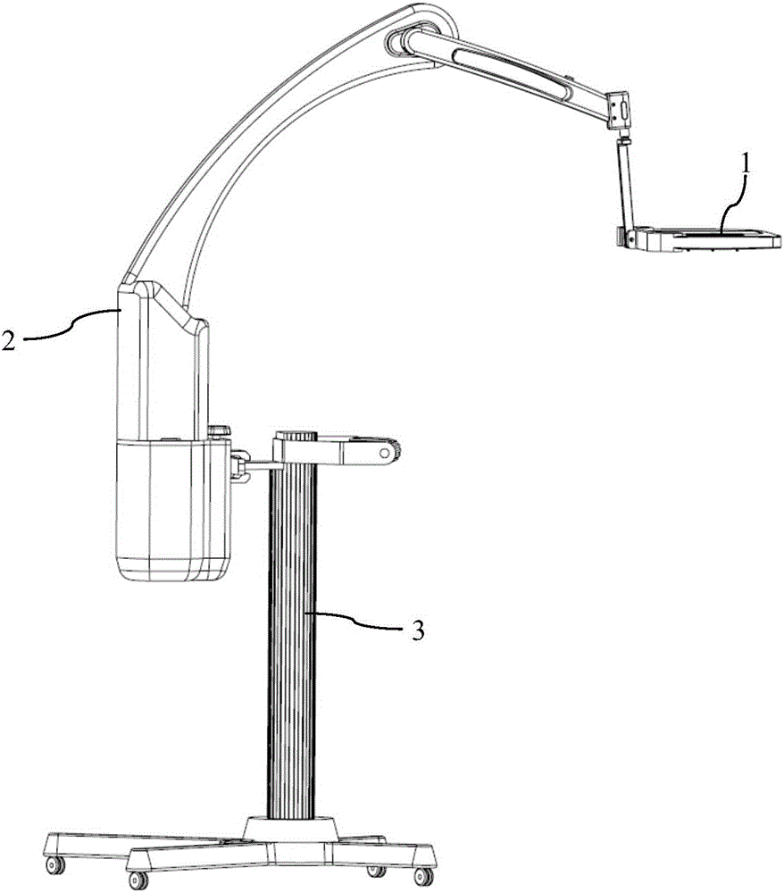
[0027] like figure 1 As shown, a simulated mechanical arm medical magnifying glass according to the present invention includes a magnifying glass 1 , a mechanical arm 2 and a trolley 3 .

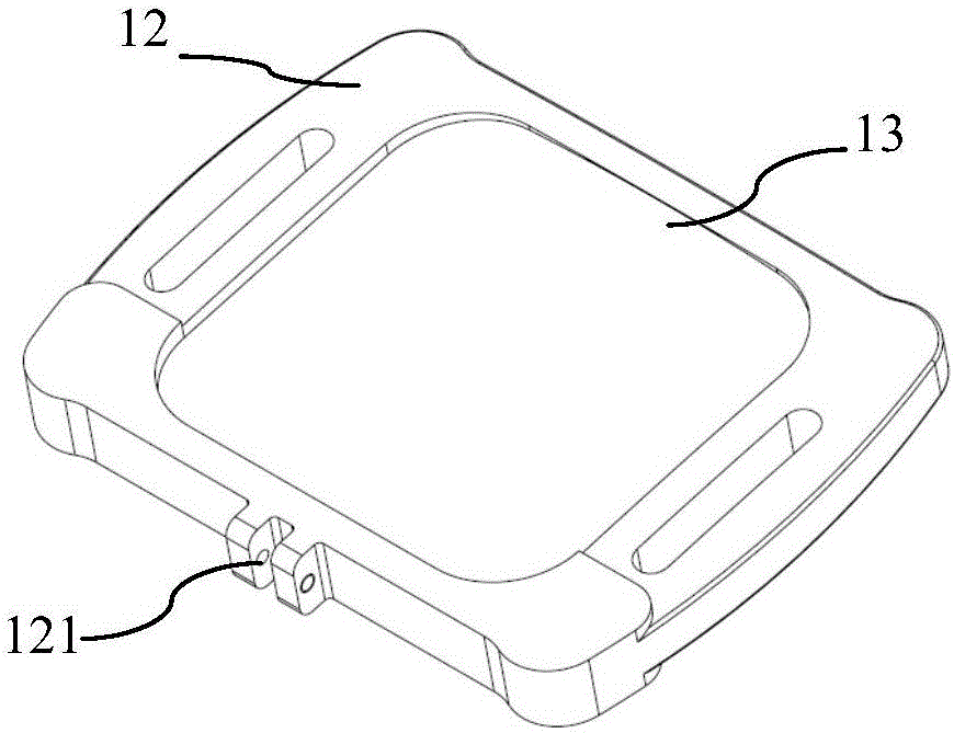
[0028] like figure 2 As shown, the magnifying glass 1 is rectangular, including a frame 12 and a mirror surface 13. The middle part of the long side of the frame 12 is provided with a bayonet 121 with the mechanical arm 2; 30cm, to ensure that there is a large enough observation field during open surgery. The mirror surface 13 is made of three or more layers of glued optical lenses to ensure that the imaging has no chromatic aberration, no aberration, and no distortion of viewing objects.

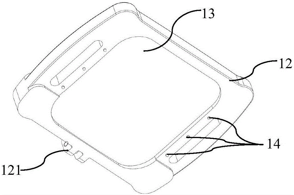
[0029] like image 3 As shown, the surgical field of view (i.e., the back side) of the magnifying glass 1 is provided with an LED cold light source 14 to ensure sufficient illum...


PUM


Abstract

The invention belongs to the technical field of medical equipment and particularly discloses a simulation mechanical arm type medical magnifying glass system. The simulation manipulator type medical magnifying glass system comprises a magnifying glass, a mechanical arm and a trolley, wherein the mechanical arm is movably connected to the trolley in a removable manner; the magnifying glass is movably connected to the mechanical arm in a removable manner; mutually-matched bayonets are respectively formed between the magnifying glass and the mechanical arm and between the trolley and the mechanical arm. The magnifying glass system disclosed by the invention has the benefits that the magnifying glass can freely move in the horizontal and vertical directions, so that the magnification is accurately adjusted, and accurate positioning is realized; the magnifying glass can also flexibly move in the non-surgical and surgical processes as required, so that a performer is not required to be within the visual field of the magnifying glass for a long time, and the vision fatigue is difficultly caused; in addition, the magnifying glass system can be controlled by not only adopting a manual control mode, but also adopting a sensor-based voice control, remote control and pedal type electronic automatic control mode, or by combining the electronic automatic control mode and the manual control mode.

Description

technical field [0001] The invention belongs to the field of medical instruments, and in particular relates to an auxiliary instrument for open surgery and ENT examination and operation, that is, a simulated mechanical arm type medical magnifying glass system. Background technique [0002] When performing some more delicate operations or inspections, such as cardiothoracic surgery and ENT surgery or inspections, it is often necessary to use a magnifying glass to magnify the surgical site by different multiples, so that the subtle structures can be seen clearly and the operation is more accurate. [0003] The magnifying glass commonly used in surgery or ENT surgery is a head-mounted medical magnifying glass. Its structure is similar to a helmet, which can be fixed on the head, and the user's entire field of view is magnified through two eyepieces with adjustable eye distance. Since the head-mounted medical magnifying glass itself has a certain weight, wearing it for a long ti...

Claims


Application Information

Patent Timeline
Patent Type & Authority Applications(China)
IPC IPC(8): A61B90/30A61B90/35G02B25/00
CPCG02B25/008
Inventor 杨柳青
Owner 重庆金创谷医疗科技有限公司
Learn More