Dust remover

A dust collector and fine dust removal technology, applied in chemical instruments and methods, dispersed particle separation, combined devices, etc., can solve the problems of affecting the ventilation effect of the dust collector, the large occupied area of ​​the dust collector, and the large amount of dust processing, and achieve the benefits of The effect of natural sedimentation, reducing the dust removal of the filter element, and reducing the floor space

Active Publication Date: 2017-02-22
玉环太平洋机械有限公司
View PDF9 Cites 9 Cited by
  • Summary
  • Abstract
  • Description
  • Claims
  • Application Information

AI Technical Summary

Problems solved by technology

However, the currently used dust collector has a particularly large dust handling capacity in some areas of the filter element, and this area is always in a blocked state, which affects the ventilation effect of the dust collector and the service life of the filter element.
The existing dust collector still has the disadvantages of large occupied area, high cost and high unit energy consumption.

Method used


Image

  • Dust remover
  • Dust remover
  • Dust remover

Examples


Embodiment 2

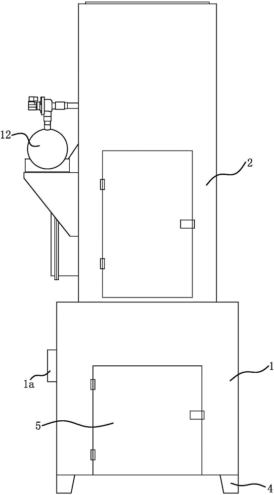
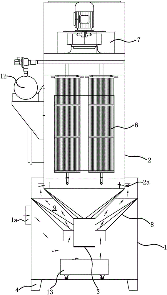
[0036] The structure and principle of this embodiment are basically the same as that of Embodiment 1, and the basic similarities will not be redundantly described, and only the differences will be described, and the differences are as follows: Figure 5 As shown, the side wall of the fine dust removal box 2 is fixedly connected with an angle iron 10, and the angle iron 10 is placed on the mouth edge of the installation connection port in the pre-dust removal box 1, and the angle iron 10 is connected with the mouth of the installation connection port in the pre-dust removal box 1. A seal is arranged along the pad between them, and the angle iron 10 and the side wall of the pre-dust removal box 1 are fixedly connected by bolts and nuts 11 . The dust collector of this structure is easy to carry, that is, the pre-dust box 1 and the fine dust box 2 are transported separately; they are assembled after reaching the destination. This structure also has the advantage of convenient assem...

Embodiment 3

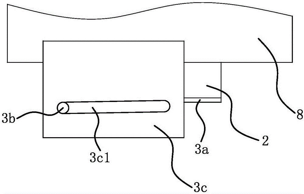
[0038] The structure and principle of this embodiment are basically the same as those of Embodiment 1, and the basic similarities will not be described redundantly, only the differences will be described, and the difference is that the ash discharge control valve 3 is an automatic ash unloader.

Embodiment 4

[0040] The structure and principle of this embodiment are basically the same as that of Embodiment 1, and the basic similarities are no longer redundantly described, and only the differences are described. The ventilation channel 9 is provided with a plurality of wind deflectors arranged helically with respect to the axis line of the ventilation pipe 8 .


PUM


Abstract

The invention provides a dust remover, belongs to the technical field of work, and solves the problems of short service life of a filter element and high unit energy consumption of the existing dust remover. The dust remover comprises a dust pre-removal box and a fine dust removal box; the bottom of the fine dust removal box is located in the dust pre-removal box; an ash discharging opening is formed in the bottom of the fine dust removal box; the dust remover further comprises an ash discharging control valve for controlling the ash discharging opening to be communicated with an inner cavity of the dust pre-removal box; a fan is arranged at the top of the fine dust removal box; the filter element is arranged in the fine dust removal box; a ventilating pipe sleeves the outer side of the bottom of the fine dust removal box; the upper end of the ventilating pipe communicates with a cavity on the outer side of the filter element in the fine dust removal box. The dust remover guarantees the spark eliminating rate, reduces the dust content of air flow entering the fine dust removal box and improves the distribution uniformity of dust in the fine dust removal box so as to guarantee the use safety of the filter element, reduce the dust removal amount of the filter element and improve the consistency of dust treatment amounts of all the filter elements; therefore, the ventilating smoothness of the filter element is improved, and the back-blowing interval of the air flow is prolonged.

Description

technical field [0001] The invention belongs to the field of operation technology, and relates to a separation device, in particular to a dust collector. Background technique [0002] A dust collector is a device used to capture and separate dust particles suspended in the air. In the production and manufacturing of metallurgy, casting, cement building materials, machinery, light industry, and electric power, it is necessary to eliminate dust pollution, protect the environment, and improve working conditions. Different working conditions produce slightly different types of dust, so people have proposed different types of dust collectors. For example, in the polishing process, especially in the polishing of bamboo and wood products, there are characteristics of large dust particles and a large amount of dust; and in the rough grinding process of stainless steel and iron parts, a large number of dust particles with sparks are produced; Pretreatment first, and then fine treat...

Claims


Application Information

Patent Timeline
Patent Type & Authority Applications(China)
IPC IPC(8): B01D50/00
CPCB01D50/20
Inventor 陈美青
Owner 玉环太平洋机械有限公司
Why Eureka
Try Eureka