Pot body pull expansion pressing mold
A technology of mold and expansion pressure, which is applied in the field of processing molds for thermos pots, can solve problems affecting product quality, unstable dimensions, and asymmetrical molding heights, so as to reduce the annealing and polishing process and avoid asymmetrical opening heights , The effect of reducing processing costs
- Summary
- Abstract
- Description
- Claims
- Application Information
AI Technical Summary
Problems solved by technology
Method used
Image

Examples
Embodiment Construction
[0017] In order to make the object, technical solution and advantages of the present invention clearer, the present invention will be further described in detail below in conjunction with the accompanying drawings.
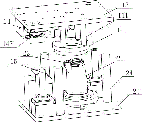
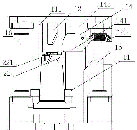
[0018] An auxetic die, comprising an upper die and a lower die, the upper die is provided with a blank holder ring 11 and an auxetic wedge 12, the flange holder ring 11 is connected to a pressure rod 111 and installed on the lower side of the upper template 13, It is used to make the outer wall of the workpiece close to the mold core 21 to complete the shaping process; the auxetic wedge 12 is installed on the lower side of the upper template 13, and the lower end of the auxetic wedge 12 is wedge-shaped; the upper side of the lower template 23 is installed There is a mold core 21 corresponding to the contour of the pot body, and the top of the mold core 21 is provided with an auxetic slider 22 on the first slide rail 221, and the position of the auxetic slider 22 co...
PUM
 Abstract
Description
Claims
Application Information
 - R&D
- Intellectual Property
- Life Sciences
- Materials
- Tech Scout
- Unparalleled Data Quality
- Higher Quality Content
- 60% Fewer Hallucinations
Browse by: Latest US Patents, China's latest patents, Technical Efficacy Thesaurus, Application Domain, Technology Topic, Popular Technical Reports.
© 2025 PatSnap. All rights reserved.Legal|Privacy policy|Modern Slavery Act Transparency Statement|Sitemap|About US| Contact US: help@patsnap.com