Electric vehicle charging switching system and control method thereof

A technology for switching systems and electric vehicles, applied in electric vehicles, battery/fuel cell control devices, vehicle energy storage, etc., can solve problems such as large fast charging current, reduced battery life, and reduced battery charging efficiency

Active Publication Date: 2018-08-21
杭州衡源汽车科技有限公司
View PDF3 Cites 0 Cited by
  • Summary
  • Abstract
  • Description
  • Claims
  • Application Information

AI Technical Summary

Problems solved by technology

[0003] However, the fast charging current is large, and charging in the fast charging mode for a long time will easily soften the battery plate, thereby reducing the service life of the battery, but reducing the charging current will reduce the charging efficiency of the battery, so there is still room for improvement

Method used


Image

  • Electric vehicle charging switching system and control method thereof
  • Electric vehicle charging switching system and control method thereof

Examples


Embodiment 1

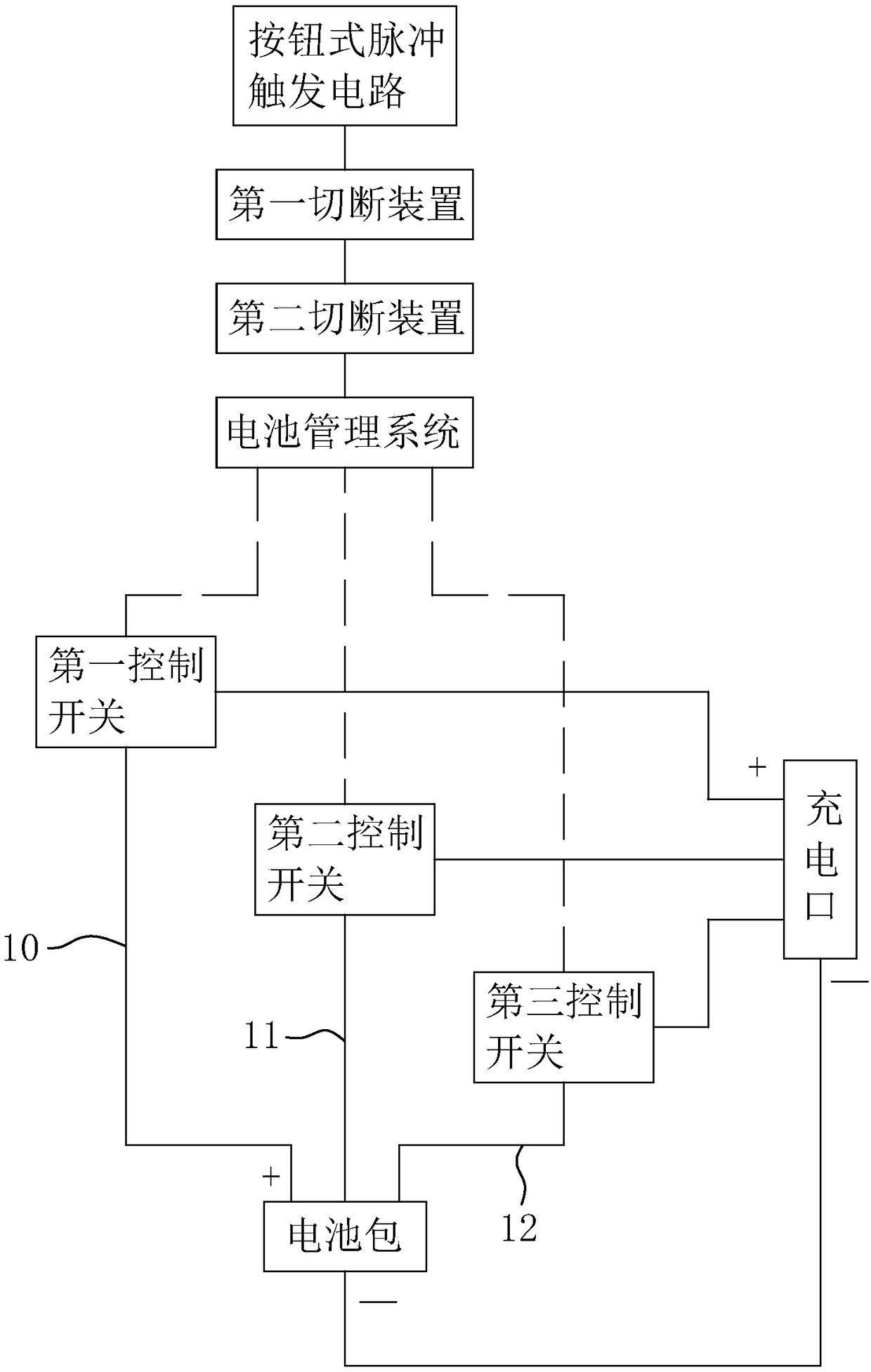
[0062] Embodiment 1, a charging switching system for an electric vehicle disclosed in this embodiment includes a battery pack 1, a charging port 4, a trigger device, a battery management system 3, and a control switch, wherein the control switch includes a first control switch 5, a second The control switch 6 and the third control switch 7.

[0063] The positive pole of the charging port 4 and the positive pole of the battery pack 1 are arranged in parallel to form a first charging circuit 10, a second charging circuit 11 and a third charging circuit 12, and the negative pole thereof is coupled to the negative pole of the battery pack 1, that is, the battery pack 1 can Charge through the three charging circuits of the first charging circuit 10, the second charging circuit 11 and the third charging circuit 12 connected to the positive pole. The charging port 4 is used to connect to an external power supply, and the electric energy of the external power supply is charged to the b...

Embodiment 2

[0072] Embodiment 2, the trigger device further includes an overcurrent detection trigger circuit, which may preferably be an integrated overcurrent detection sensor chip.

[0073] The over-current detection trigger circuit is used to monitor the current change of the negative pole of the charging port 4 to output a corresponding over-current detection signal to the battery management system 3. When the battery pack 1 is in the process of normal charging, the current flowing through the negative pole of the charging port 4 The current is less than the standard current value.

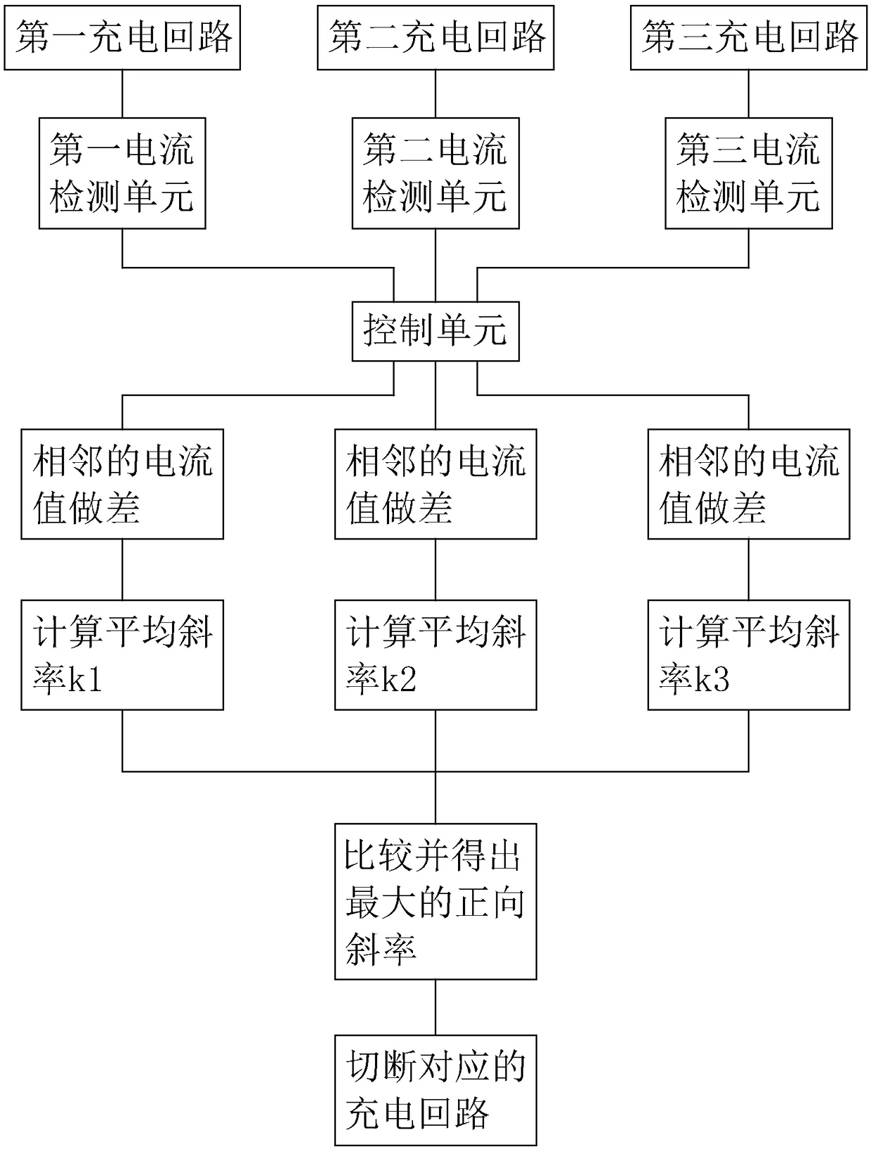
[0074] Conversely, when the battery pack 1 is being charged, if an overcurrent phenomenon occurs in the first charging circuit 10, the second charging circuit 11 or the third charging circuit 12, the current flowing through the negative pole of the charging port 4 will be greater than the standard current value. At this time, the circuit with overcurrent fault in the first charging circuit 10, the secon...

Embodiment 3

[0077] Embodiment 3, on the basis of Embodiment 2, the overcurrent detection trigger circuit also has a reference value, which corresponds to the standard current value when the negative pole of the charging port 4 is working normally, and the standard current value is lower than the limit current value. When the battery pack 1 is in the process of fast charging, if there is a slight overcurrent phenomenon, that is, the current of the negative pole of the charging port 4 is higher than the standard current value but lower than the limit current value, the battery pack will not be damaged in a short time 1, but it is not suitable to keep the battery pack 1 in this state for a long time. If the first charging circuit 10, the second charging circuit 11 and the third charging circuit 12 are directly cut off at this time, although the overcurrent fault can be resolved in time, However, the battery pack 1 cannot continue to be charged, thereby affecting the charging efficiency.

[0...


PUM


Abstract

The invention discloses a charging switching system of an electric vehicle and a control method thereof. The problem that too low charging speed affects the efficiency but too high easily cause battery loss is solved. According to the technical scheme, the charging switching system is characterized by comprising a battery pack, a triggering device, a battery management system, a charging port, a first control switch, a second control switch and a third control switch. According to the charging switching system of the electric vehicle and the control method, three charging loops are formed between the charging port and a positive pole of the battery pack, the charging rate of the battery pack can be adjusted by adjusting the breakover number of the charging loops, the breakover number of the charging loops is larger, the higher the charging rate of the battery pack is, and the three control switches can control breakover of corresponding charging loops. The charging rate of the battery pack can be adjusted as required. When the charging rate is needed to be improved, breakover of the three breakover loops can be performed; conversely, when the battery pack is needed to be maintained, the breakover number of the charging loops is decreased to reduce battery damage.

Description

technical field [0001] The invention relates to an electric vehicle, in particular to a charging switching system and a control method for the electric vehicle. Background technique [0002] With the advancement of science and technology, the increasing scarcity of oil resources and the improvement of public awareness of environmental protection, electric vehicles have attracted more and more attention. However, there are still corresponding technical bottlenecks in electric vehicles at present, especially because of battery performance and short cruising range, which cannot meet the requirements of consumers. There is still a certain gap between the current battery performance and the customer's requirements. Even if the battery capacity is increased to meet the customer's requirements, it will inevitably cause an increase in the cost of the entire vehicle of the electric vehicle, making the economy of the electric vehicle compared with the traditional gasoline vehicle Gre...

Claims


Application Information

Patent Timeline
Patent Type & Authority Patents(China)
IPC IPC(8): B60L11/18
CPCB60L58/10B60L58/12Y02T10/70
Inventor 王祖光钟巍
Owner 杭州衡源汽车科技有限公司
Why Eureka
Try Eureka