Spatial efficient heat transfer micropump-driven fluid loop apparatus

A technology for driving fluid and heat transfer, which is applied in transportation and packaging, devices for controlling the living conditions of aerospace vehicles, motor vehicles, etc. It can solve problems such as poor adaptability, poor adaptability to changes, and inability to transfer heat, so as to achieve precise temperature control , large heat regulation capability, and the effect of flexible thermal management functions

Inactive Publication Date: 2017-02-22
SHANGHAI SATELLITE ENG INST
View PDF4 Cites 2 Cited by
  • Summary
  • Abstract
  • Description
  • Claims
  • Application Information

AI Technical Summary

Problems solved by technology

[0003] Usually, satellites use embedded heat pipes to achieve isothermal design of instrument panels and heat collection, mainly relying on radiation heat transfer to realize heat transmission and dissipation. This thermal design method has poor adaptability to changes in orbital heat flow and internal power consumption. The heat transfer efficiency is low and it is not easy to solve the heat dissipation problem of a single machine with high power consumption; active thermal control technologies such as electric heaters can only compensate the temperature of low-temperature areas, and cannot perform heat transfer and dissipation; passive thermal control technologies such as multi-layer and coating are also the same. Poor adaptability to changes in heat flow outside the orbit and internal power consumption, unable to adapt to the development of missions such as deep space probes, inclined orbit satellites, SAR series satellites, and high-power communication satellites

Method used


Image

  • Spatial efficient heat transfer micropump-driven fluid loop apparatus
  • Spatial efficient heat transfer micropump-driven fluid loop apparatus

Examples


Embodiment Construction

[0019] The present invention will be described in detail below in conjunction with specific embodiments. The following examples will help those skilled in the art to further understand the present invention, but do not limit the present invention in any form. It should be noted that those skilled in the art can make several modifications and improvements without departing from the concept of the present invention. These all belong to the protection scope of the present invention.

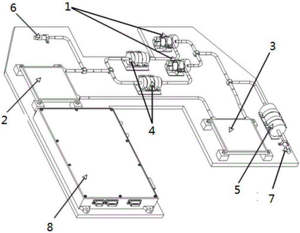
[0020] Such as figure 1 As shown, the embodiment of the present invention provides a space-efficient heat transfer micropump driving fluid circuit, including an integrated mounting board, a micropump controller 8, two micropumps 1, a first thermal pillow 2, a second thermal pillow 3, A liquid reservoir 5, two one-way valves 4, a φ6mm stainless steel pipe with a wall thickness of 1mm and matching tees, an air charging valve 7 and a liquid filling valve 6; integrated installation board, a micropump ...


PUM


Abstract

The invention provides a spatial efficient heat transfer micropump-driven fluid loop, made by welding and integrating an integrated mounting board, a micropump controller, two micropumps, a first heat sink, a second heat sink, a liquid storage device, two one-way valves, stainless steel pipes and supporting tees; the two micropumps and the two one-way valves are two independently parallel paths, backup for each other; the two micropumps are connected to the first heat sink, the second heat sink, the two one-way valve and the liquid storage device respectively through the stainless steel pipes and the supporting tees, and the two one-way valves are mounted respectively between the two micropumps and the first heat sink and liquid filling valve; one end of the liquid storage device is connected to an inflating valve though a stainless steel pipe, the inflating valve and the liquid filling valve are connected to the stainless steel pipe respectively through ferrules, the micropump controller is connected with the two micropumps, and the micropump controller controls a thermal switch and controls heat transfer by controlling start-stop and speed of the micropumps. Heat is quickly transferred between the heat sinks through micropump-driven medium water, the function of quickly balancing temperature differences is provided, and high adaptability to changes in extra-rail heat flow and inner power consumption is provided.

Description

technical field [0001] The invention relates to an aircraft thermal control device, in particular to a space-efficient heat transfer micropump driving fluid circuit. Background technique [0002] With the development of future space missions, thermal control technology is facing new severe challenges for the increasingly harsh and complex space application environment and the development needs of multi-functional and multi-mission aircraft platforms. Conventional thermal control design concepts based on passive thermal control technologies such as multi-layers and coatings, supplemented by active thermal control technologies such as electric heaters, have been unable to meet the needs of ever-changing task development. The new thermal control technology represented by the active fluid circuit thermal control technology is widely used in manned spaceflight, space station, deep space exploration, High-power communication satellites and other fields have been widely demonstrat...

Claims


Application Information

Patent Timeline
Patent Type & Authority Applications(China)
IPC IPC(8): B64G1/50B64G1/10
CPCB64G1/50B64G1/10B64G1/1007B64G1/105
Inventor 曹建光陈钢顾燕萍孙伟伟王江徐涛王涛刘冈云叶沙琳
Owner SHANGHAI SATELLITE ENG INST
Why Eureka
Try Eureka