Integrated A2O improvement system

A technology of aerobic zone and secondary sedimentation tank, which is applied in A2O and oxidation ditch to improve A2O in an integrated way. ,A2O combined with the oxidation ditch field can solve the problems of high investment and operating costs, low impact load resistance, and unfavorable phosphorus removal, and achieve the effect of reducing operating costs, reducing impacts, and saving investment

Pending Publication Date: 2017-02-22
LINGZHI ENVIRONMENTAL PROTECTION CO LTD +2
View PDF2 Cites 3 Cited by
  • Summary
  • Abstract
  • Description
  • Claims
  • Application Information

AI Technical Summary

Problems solved by technology

Traditional A 2 The O process is a fully mixed bioreactor, which consists of anaerobic, anoxic, and aerobic stages, and has a low impact load resistance; the return sludge directly enters the anaerobic zone, which affects the anaerobic environment in the anaerobic tank, and the nitrogen content Denitrification and anaerobic phosphorus release compete with each other, which is unfavorable for phosphorus removal; and the secondary sedimentation tank and A 2 O The reaction tank is built separately, and the sludge return pump room needs to be built separately, which occupies a large area and has high investment and operating costs.

Method used


Image

  • Integrated A2O improvement system
  • Integrated A2O improvement system

Examples


Embodiment 1

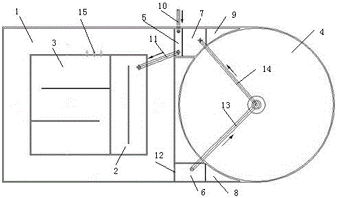
[0012] Embodiment 1: Integrated improvement A 2 O system, including the aerobic zone 1, the aerobic zone 1 is set in an annular ditch structure, the anaerobic zone 2 and the anoxic zone 3 are set in the center of the aerobic zone 1 ring ditch, and the side of the aerobic zone 1 is set with a secondary sedimentation tank 4 , the sandwich area between the secondary settling tank 4 and the aerobic zone 1 is divided into an influent mixing zone 5, a secondary settling tank inflow zone 6, a sludge return zone 7, an effluent zone 8, and a slag clear liquid discharge zone 9. The water pipe 10 is connected to the water inlet mixing area 5, and the water inlet mixing area 5 mixes the water entering the water inlet mixing area 5 with the return sludge transported by the sludge return area 7 through the first pipeline 11 and enters the anaerobic area 2, and the anaerobic area 2 The sewage enters the anoxic zone 3 through holes, and the sewage in the anoxic zone 3 enters the aerobic zone ...

Embodiment 2

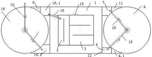
[0013] Embodiment 2: Integrated improvement A 2 O system, including aerobic zone 1, aerobic zone 1 is set in an annular ditch structure, anaerobic zone 2 and anoxic zone 3 are set in the center of the aerobic zone 1 circular ditch, and primary sedimentation tanks are set on both sides of aerobic zone 1 16 and the secondary settling tank 4, the area between the primary settling tank 16 and the aerobic zone 1 is divided into the primary settling tank effluent area 16.1, the primary settling tank sludge discharge area 16.2, the slag clear liquid discharge area 9, and the secondary settling tank 4 and the aerobic zone 1 are divided into secondary settling tank outlet area 4.1, slag liquid discharge area 9, sludge return area 7, secondary settling tank inlet area 6, and water inlet pipe 10 connected to the primary settling tank 16. The sludge produced in the primary sedimentation tank 16 enters the sludge discharge area 16.2 of the primary sedimentation tank through the fourth pipe...


PUM


Abstract

The invention discloses an integrated A2O improvement system, and belongs to the technical field of water treatment. The system comprises an inlet water mixing area, an anaerobic zone, an anoxic zone, an aerobic zone, a secondary sedimentation tank water inlet area, a secondary sedimentation tank, a sludge return area, an effluent area and a residue supernatant discharge area. According to the traditional A2O process, and with the combination of sewage flow state in an oxidation ditch process, the secondary sedimentation tank and an improved A2O pool are built together by combining a sewage flow state of an oxidation ditch process. According to the process, the joint area formed by joint building is fully utilized, so that multiple structure functions are integrated, the floor area is greatly reduced, the pipeline loss is reduced, the investment is reduced, the operating cost is reduced, the advantages of the A2O and oxidation ditch process are combined, the change requirements of the water quality and water quantity are met, the technological adaptability is high, and the system is attractive and practical.

Description

technical field [0001] The present invention relates to A 2 O and oxidation ditch belong to the technical field of water treatment, especially a kind of A 2 O combines the oxidation ditch, sets the aerobic zone as an annular ditch, and combines the sedimentation tank with the improved A 2 O The integrated improvement of process integration A 2 O. Background technique [0002] Sewage treatment biochemical process is generally divided into A 2 O, oxidation ditch, SBR, etc. Traditional A 2 The O process is a fully mixed bioreactor, which consists of anaerobic, anoxic, and aerobic stages, and has a low impact load resistance; the return sludge directly enters the anaerobic zone, which affects the anaerobic environment in the anaerobic tank, and the nitrogen content Denitrification and anaerobic phosphorus release compete with each other, which is unfavorable for phosphorus removal; and the secondary sedimentation tank and A 2 The O reaction pool is built separately, and t...

Claims


Application Information

Patent Timeline
Patent Type & Authority Applications(China)
IPC IPC(8): C02F3/30
CPCC02F3/302C02F2203/006C02F2301/046
Inventor 刘宝华汪文丽周玮程鹏飞刘会平张冬
Owner LINGZHI ENVIRONMENTAL PROTECTION CO LTD
Why Eureka
Try Eureka