
Incoming water pretreatment device for constructed wetland system and method thereof

A technology of constructed wetland system and pretreatment device, which is applied in the direction of aerobic process treatment, biological water/sewage treatment, water/sludge/sewage treatment, etc. Sufficient, high economic cost and other issues, to achieve the effect of improving water quality, avoiding water hammer effect, and reducing the occupied area

Inactive Publication Date: 2017-02-22
星景生态环保科技(苏州)有限公司
View PDF0 Cites 0 Cited by
  • Summary
  • Abstract
  • Description
  • Claims
  • Application Information

AI Technical Summary

Problems solved by technology

Currently commonly used pretreatment facilities include sedimentation tanks, anaerobic reactors (such as anaerobic baffle reactors and downflow anaerobic suspended packed beds), biological contact oxidation ponds and oxidation ponds, etc., but these facilities have low removal rates. , high economic cost, insufficient removal of organic matter, inability to effectively reduce the footprint of subsequent constructed wetlands, etc.

Method used


Image

  • Incoming water pretreatment device for constructed wetland system and method thereof
  • Incoming water pretreatment device for constructed wetland system and method thereof
  • Incoming water pretreatment device for constructed wetland system and method thereof

Examples


Embodiment 1

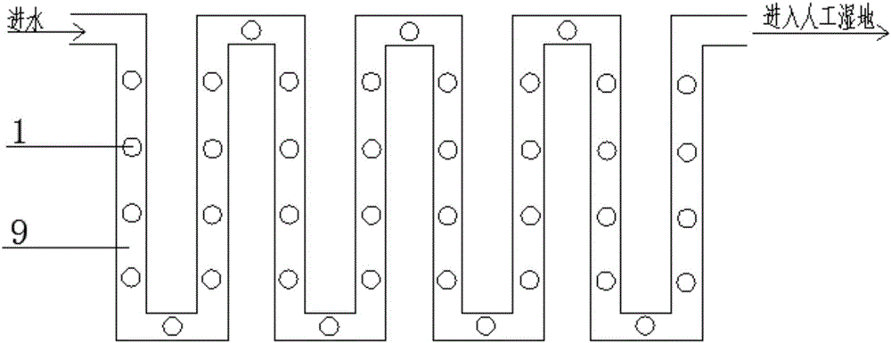
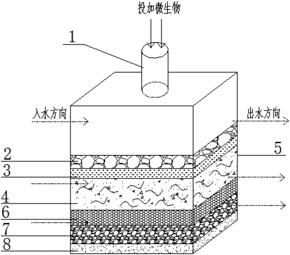
[0027] Embodiment 1, reference figure 1 and image 3 .

[0028] Including a square pipe 5, the bottom of the square pipe 5 is provided with a packing layer, the height of the packing layer accounts for 2 / 3 of the height of the square pipe 5, and the packing layer is divided into a physical filter layer and an earthworm filter layer from bottom to top , a circular air vent 1 is provided directly above the square pipe 5 .

[0029] The physical filter layer is a fine sand layer 8, a vermiculite layer 7 and a ceramsite layer 6 from bottom to top.

[0030] The earthworm filter layer includes humus layer 4, fiber layer 3 and gravel layer 2 from bottom to top.

[0031] The height*width of the cross section of the square pipe 5 is (0.8-1.2)m*(0.5-0.7)m, the height of the upper part of the square pipe 5 is 0.25-0.35m, and the thickness of the earthworm filter layer is 0.3- 0.5m, the thickness of the physical filter layer is 0.25-0.35m.

[0032] The thickness of the fine sand layer...

Embodiment 2

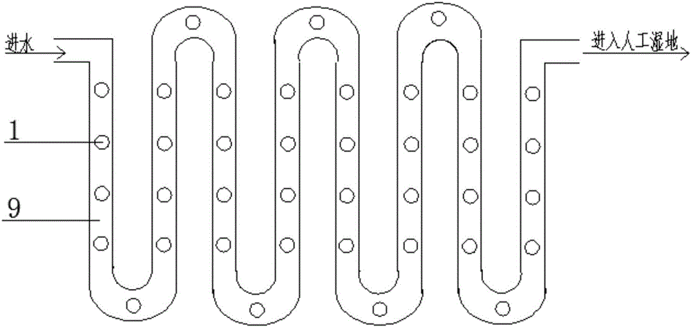
[0042] Embodiment 2, refer to figure 2 and image 3 .

[0043] Including a square pipe 5, the bottom of the square pipe 5 is provided with a packing layer, the height of the packing layer accounts for 2 / 3 of the height of the square pipe 5, and the packing layer is divided into a physical filter layer and an earthworm filter layer from bottom to top , a circular air vent 1 is provided directly above the square pipe 5 .

[0044] The physical filter layer is a fine sand layer 8, a vermiculite layer 7 and a ceramsite layer 6 from bottom to top.

[0045] The earthworm filter layer includes humus layer 4, fiber layer 3 and gravel layer 2 from bottom to top.

[0046] The height*width of the cross section of the square pipe 5 is (0.8-1.2)m*(0.5-0.7)m, the height of the upper part of the square pipe 5 is 0.25-0.35m, and the thickness of the earthworm filter layer is 0.3- 0.5m, the thickness of the physical filter layer is 0.25-0.35m.

[0047] The thickness of the fine sand layer...


PUM

PropertyMeasurementUnit
Thicknessaaaaaaaaaa
Thicknessaaaaaaaaaa
Thicknessaaaaaaaaaa

Abstract

The invention relates to a water inlet treatment device for a constructed wetland system and a method thereof, and particularly relates to an incoming water pretreatment device for a constructed wetland system and a method thereof. The device comprises a square pipeline, wherein a filling layer is arranged at the bottom of the square pipeline, and is two thirds as high as the square pipe; the filling layer is divided into a physical filter layer and an earthworm filter layer from bottom to top; a round vent is formed right above the square pipeline. According to the method, after the device is applied to a grating and a grit chamber, sands and large particles in sewage are removed, and the sewage enters a sewage delivery pipeline of the device and flows through the earthworm filter layer and the physical filter layer in the delivery process, so that organic matters and solid pollutants in the sewage are further purified.

Description

technical field [0001] The invention relates to a water inlet device and method for a constructed wetland system, in particular to a water inlet pretreatment device and method for a constructed wetland system. Background technique [0002] As the main sewage ecological restoration technology, constructed wetland is widely used to treat various forms of sewage due to its ecological and environmental friendliness. [0003] At present, the constructed wetlands used at home and abroad generally have the disadvantage of insufficient long-term operation stability of the system (that is, the pores of the planting bed are easily blocked). The main reason is the insufficient removal of suspended solids in the water during the pretreatment process or the compaction of the planting bed medium caused by plant root exudates. Currently commonly used pretreatment facilities include sedimentation tanks, anaerobic reactors (such as anaerobic baffle reactors and downflow anaerobic suspended ...

Claims


Application Information

Patent Timeline
IPC IPC(8): C02F3/32C02F3/02C02F3/34
CPCC02F3/02C02F3/32C02F3/34Y02W10/10
Inventor 高彦波郭宏凯王婉清郑晓慧杨育
Owner 星景生态环保科技(苏州)有限公司
Learn More