A formwork composite structure for cast-in-place walls and its construction method
A cast-in-place wall and combined structure technology, applied in the direction of formwork/formwork/work frame, formwork/formwork/work frame connector, on-site preparation of building components, etc., can solve the problem of high labor intensity, formwork support, etc. High cost, large dangerous system and other problems, to achieve the effect of low labor intensity, convenient construction and low labor intensity
- Summary
- Abstract
- Description
- Claims
- Application Information
AI Technical Summary
Problems solved by technology
Method used
Image
Examples
Embodiment 1
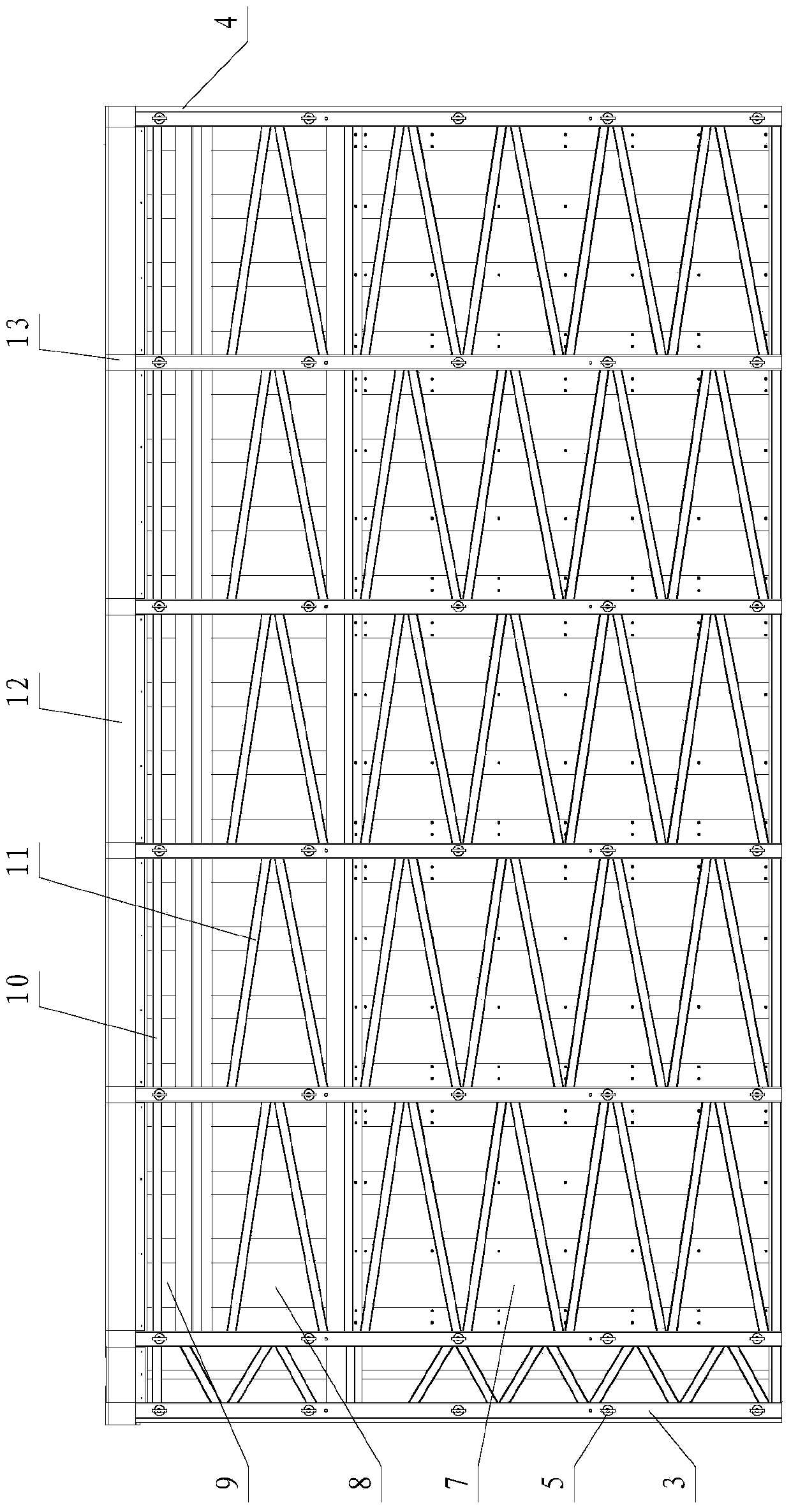
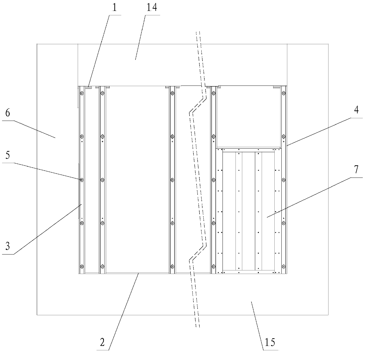
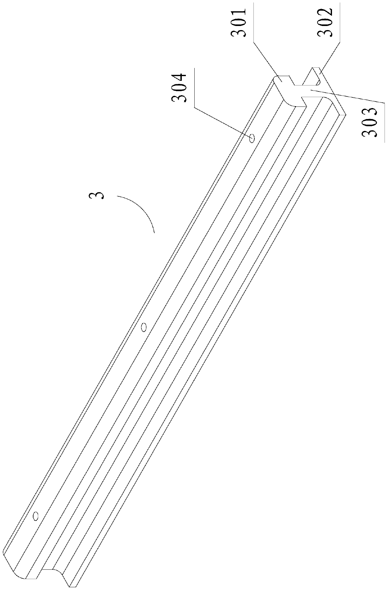
[0070] Such as figure 1 , figure 2 As shown, the formwork combination structure of the present invention includes an upper limit wooden strip 1, a lower limit wooden strip 2, a wood-plastic composite column 3, an EPE foam board 4, a connecting assembly 5, a formwork assembly, a support rod and a pouring belt 12, wherein the formwork assembly includes The lower formwork 7, the middle formwork 8 and the top formwork 9, the support bars include support cross bars 10 and support slant bars 11; between the upper beam 14 of the wall 6, the ground 15 and the columns on both sides is the cast-in-place wall to be poured body.
[0071] The both sides of the upper beam 14 lower surface are respectively equipped with an upper limit wooden strip 1, and two lower limit wooden strips 2 are installed on the ground 15, and the lower limit wooden strip 2 controls the size of the actual pouring wall body, and the lower limit wooden strip 2 Length is the length of actual pouring body of wall, ...
Embodiment 2
[0092] The difference between the present embodiment and the first embodiment is that in the first embodiment, the upper and lower ends of the wood-plastic composite column 3 lean against the upper and lower limit wooden strips 1 and 2 respectively, while the present embodiment does not have the upper and lower limit wooden strips 1 and 2 are to install multiple keel components on the wall 6, such as Figure 20 As shown, the keel components include keel A16, keel B17 and keel C18, the keel A16 is installed on the upper beam 14, the keel C18 is installed on the ground 15, the keel A16 and the keel C18 are connected with the keel B17; The end leans against the keel A16 and the keel C18 of the upper beam 14 and the ground 15 respectively. A support bar 10 is installed on the ground 15, the bottom of the lower formwork 7 and the support bar 10 on the ground 15 are overlapped by a Z-shaped notch, and a casting belt is left between the top formwork 9 and the keel A16 of the upper be...
PUM
 Abstract
Description
Claims
Application Information
 - R&D
- Intellectual Property
- Life Sciences
- Materials
- Tech Scout
- Unparalleled Data Quality
- Higher Quality Content
- 60% Fewer Hallucinations
Browse by: Latest US Patents, China's latest patents, Technical Efficacy Thesaurus, Application Domain, Technology Topic, Popular Technical Reports.
© 2025 PatSnap. All rights reserved.Legal|Privacy policy|Modern Slavery Act Transparency Statement|Sitemap|About US| Contact US: help@patsnap.com


