Spindle seal pressure steel pipe side water supply pipeline of water turbine unit

A technology of spindle sealing and pressure steel pipes, which is applied in hydropower, machines/engines, mechanical equipment, etc., can solve problems such as large vibration of water supply pipelines, inconsistent design pressure, and failure to decompress normally, so as to ensure safe and stable operation and eliminate Existing defects, effect of eliminating sediment clogging

Pending Publication Date: 2017-02-22
STATE GRID CORP OF CHINA +2
View PDF7 Cites 1 Cited by
  • Summary
  • Abstract
  • Description
  • Claims
  • Application Information

AI Technical Summary

Problems solved by technology

Since the units of Zhanghewan Pumped Storage Power Station in Hebei Province were put into operation, the system has been found to have the following defects: ① There is no filter at the inlet of the pressure reducing valve, which often leads to blockage of the valve core of the pressure reducing valve, so that the pressure cannot be reduced normally
②The decompression effect is not ideal. After the unit has been running for a period of time, due to the vibration of the unit, the pressure after decompression does not match the design pressure, and the pressure relief valve needs to be manually adjusted.
③The water supply pipeline vibrates greatly. Due to the unsatisfactory decompression effect, the safety valve near the electric valve at the outlet of the pipeline operates frequently to release the pressure.
[0004] The above technologies have not given specific guidance on how to make the main shaft of the hydraulic turbine unit seal the pressure steel pipe side water supply pipeline, how to eliminate or reduce the pipeline vibration caused by pressure adjustment, and eliminate the sediment blockage in the pipeline

Method used


Image

  • Spindle seal pressure steel pipe side water supply pipeline of water turbine unit
  • Spindle seal pressure steel pipe side water supply pipeline of water turbine unit

Examples


Embodiment Construction

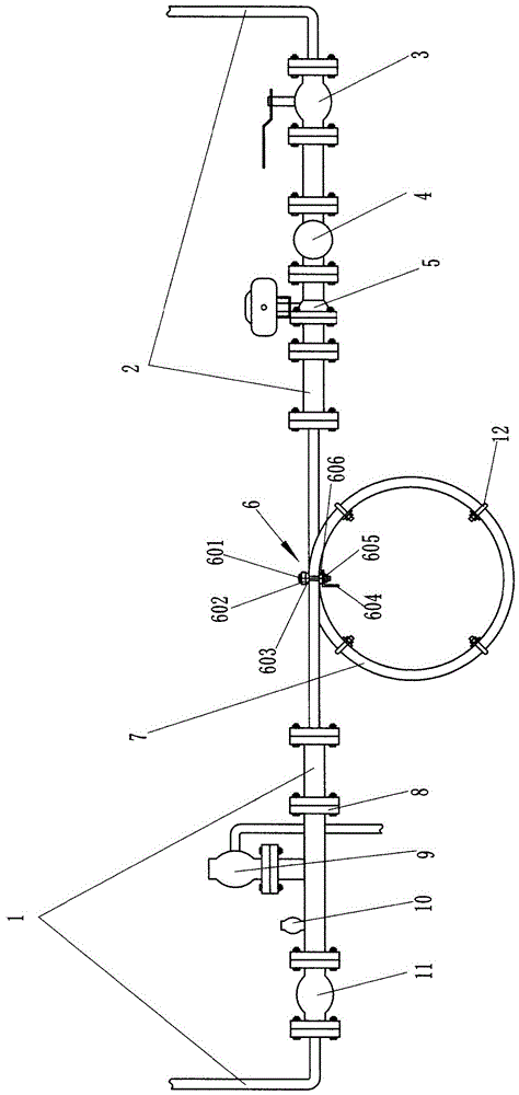
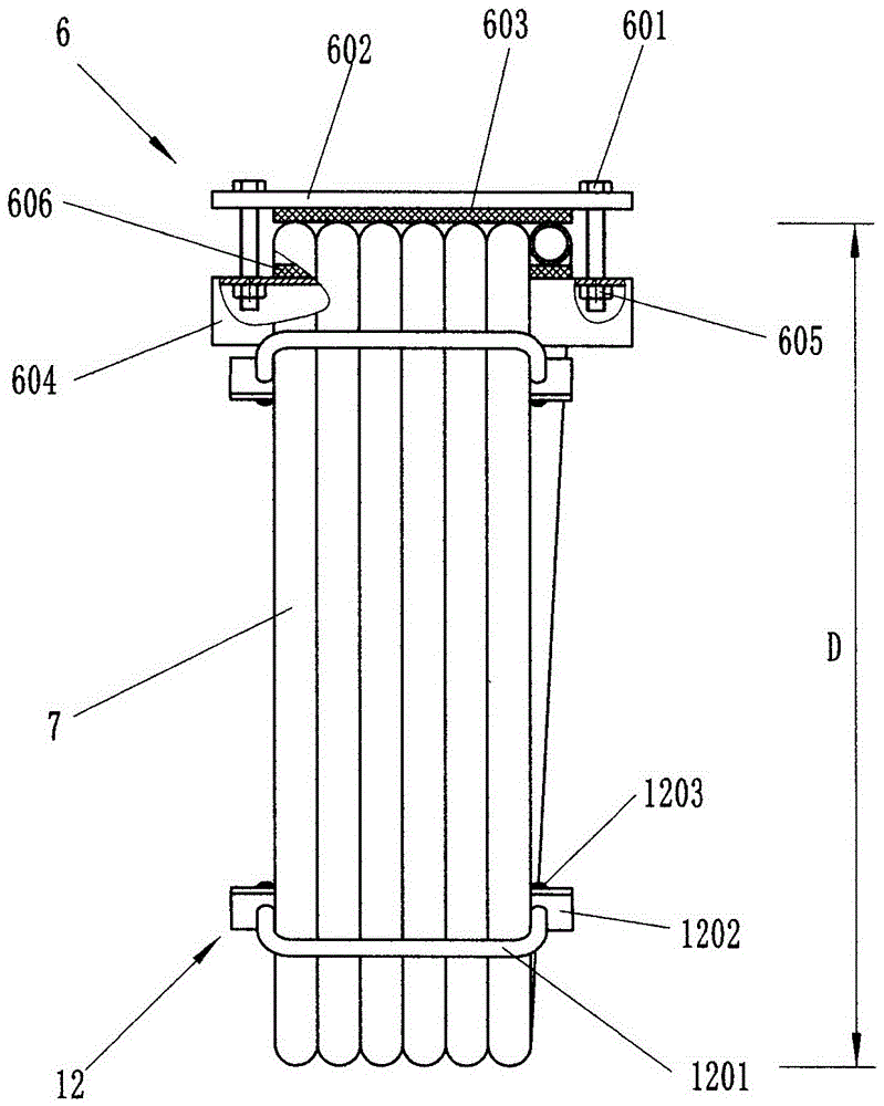
[0013] Such as figure 1 , figure 2 As shown, the main shaft sealing pressure steel pipe side water supply pipeline of the hydraulic turbine unit of the present invention has a left side water supply pipe 1, a right side water supply pipe 2, an electric valve 5, a water intake main valve 3 are installed on the right side water supply pipe 2, and a left side water supply pipe An intermediate flange 8 , a pressure relief valve 9 , a safety valve 10 and a connecting valve 11 are installed on the pipe 1 . The left water supply pipe 1 and the right water supply pipe 2 are connected with a decompression ring pipe 7 through a flange, that is, the water inlet and the water outlet of the decompression ring pipe 7 are respectively connected to the right water supply pipe 2 and the right water supply pipe 2 through a flange. Left water supply pipe 1. The decompression ring pipe 7 is limited by several positioning cards 12 that prevent it from extending outward (extending along the axia...


PUM


Abstract

A spindle seal pressure steel pipe side water supply pipeline of a water turbine unit comprises a left-side water supply pipe and a right-side water supply pipe; an electric valve and a main water taking valve are mounted on the right-side water supply pipe; an intermediate flange, a pressure relief protection valve, a safety valve and a connecting valve are mounted on the left-side water supply pipe; the pipeline is characterized in that a circular pressure reducing pipe is connected between the left-side water supply pipe and the right-side water supply pipe through a flange; the circular pressure reducing pipe is limited by a plurality of positioning clips for preventing the circular pressure reducing pipe from extending outwards and is mounted on a suspending supporting body; and a filter is mounted on the right-side water supply pipe and is located between the main water taking valve and the electric valve. Pipeline vibration caused by pressure adjustment can be eliminated or reduced with the spindle seal pressure steel pipe side water supply pipeline, and the phenomenon of sediment blockage inside the pipeline is eliminated. According to the pipeline, transformation is performed on the basis of existing equipment layout, the work quantity is small, and the transformation cost is saved.

Description

technical field [0001] The invention relates to a main shaft sealing water supply system of a water turbine unit, in particular related to the structure of the main shaft sealing pressure steel pipe side water supply pipeline of the water turbine unit, in particular to a main shaft sealing pressure steel pipe side water supply pipeline of the water turbine unit. Background technique [0002] Hebei Zhanghewan Pumped Storage Power Station has an installed capacity of 1 million kW, and installed four 250,000 kW single-stage mixed-flow reversible pump-turbine generator sets. The annual design power generation is 1.675 billion KWh, and the annual pumping power consumption is 2.204 billion KWh , the comprehensive efficiency of the power station is 0.76. In the power grid, the power station is mainly responsible for tasks such as peak regulation, valley filling, frequency regulation, phase regulation and spinning reserve. The water turbine is a vertical shaft single-stage reversib...

Claims


Application Information

Patent Timeline
Patent Type & Authority Applications(China)
IPC IPC(8): F03B11/00F03B11/04F03B11/08F03B13/06
CPCF03B11/006F03B11/04F03B11/08F03B13/06Y02P90/50Y02E10/20Y02E60/16
Inventor 陈波朱海峰王国柱李甲骏任刚潘雪石李永红李永杰赵一炜赵雪鹏
Owner STATE GRID CORP OF CHINA
Why Eureka
Try Eureka