Hydraulic circuit of the differential telescopic system and aerial work platform using hydraulic circuit of the differential telescopic system

A hydraulic circuit, differential technology, applied in the servo meter circuit, fluid pressure actuating device, lifting device, etc., can solve the problems of high price of air-permeable structure balance valve, increase the difficulty of valve body layout, and inability to open the balance valve. , to achieve the effect of improving the performance of the host product, low sealing requirements, and reducing the cross-section of the boom

Inactive Publication Date: 2017-02-22
XCMG FIRE FIGHTING SAFETY EQUIP CO LTD
View PDF9 Cites 11 Cited by
  • Summary
  • Abstract
  • Description
  • Claims
  • Application Information

AI Technical Summary

Problems solved by technology

[0009] 1. Use double solenoid valves to switch, which will increase the difficulty of valve body layout. At the same time, an additional valve hole is required for valve body processing, which is not good for quality control. At the same time, double solenoid valves will increase the cost;
[0010] 2. The air-permeable balance valve must be selected, because the oil return of the rod chamber is connected with the oil inlet of the non-rod chamber during the extension pro...

Method used


Image

  • Hydraulic circuit of the differential telescopic system and aerial work platform using hydraulic circuit of the differential telescopic system
  • Hydraulic circuit of the differential telescopic system and aerial work platform using hydraulic circuit of the differential telescopic system

Examples


Embodiment Construction

[0035] The present invention will be further described below in conjunction with accompanying drawing.

[0036] The following will clearly and completely describe the technical solutions in the embodiments of the present invention with reference to the accompanying drawings in the embodiments of the present invention. Obviously, the described embodiments are only some, not all, embodiments of the present invention. Based on the embodiments of the present invention, all other embodiments obtained by persons of ordinary skill in the art without making creative efforts belong to the protection scope of the present invention.

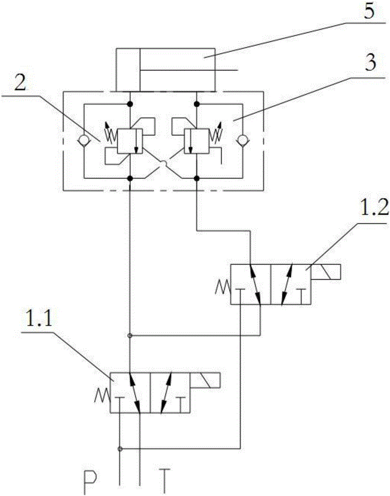
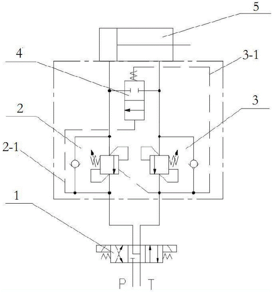
[0037] As shown in Figure 3, it is a differential telescopic system hydraulic circuit, which includes:

[0038] Single solenoid valve 1;

[0039] The solenoid valve 1 communicates with the rodless cavity and the rod cavity of the telescopic cylinder 5 through the rodless cavity balance valve 2 and the rod cavity balance valve 3 respectively;

[0040] A hy...


PUM


Abstract

This invention discloses the hydraulic circuit of the differential telescopic system. The hydraulic circuit of the differential telescopic system includes the single solenoid valve (1), which passes through the balance valve without the rod cavity (2) and the balance valve with the rod cavity (3) connecting with the rod cavity of the telescopic cylinder (5) and the rodless cavity of the telescopic cylinder (5). The hydraulic check valve (4) is installed between the balance valve without the rod cavity (2) and the balance valve with the rod cavity (3). The controllable oil circuit I is formed between the balance valve without the rod cavity (2) and the hydraulic check valve (4). The controllable oil circuit II is formed between the balance valve with the rod cavity (3) and the hydraulic check valve (4). The hydraulic circuit of the differential telescopic system also includes the aerial work platform adopting the hydraulic circuit of the differential telescopic system. The hydraulic circuit of the differential telescopic system uses the single solenoid valve, which will not increase the difficulty of arranging the valve. The balance valve is the ordinary one, which can reduce the cost effectively. Meanwhile, the hydraulic control valve, which will automatically switch the differential function, can improve the telescopic efficiency. The full working process of this hydraulic circuit of the differential telescopic system will not pollute the air for the reason that there will be no leakage of the oil without hydraulic pressure.

Description

technical field [0001] The invention relates to a hydraulic circuit of a differential telescopic system and an aerial work platform using the circuit. Background technique [0002] If the boom of the aerial work platform wants to realize the telescopic function, it must be driven by the hydraulic cylinder. However, the rodless chamber of the general telescopic cylinder has a large volume. In order to ensure that the vehicle has a fast enough telescopic speed, it is necessary to choose a large flow. Oil pumps and control valves, and if the flow requirements for other actions of the vehicle are relatively small, it will cause waste of oil pump and engine power; [0003] At the same time, the selection of components with large flow rate will also increase the cost of the product. Therefore, in order to ensure a faster speed under the condition of small flow supply, a differential circuit is generally used, and the traditional differential control circuit requires a rod cavity b...

Claims


Application Information

Patent Timeline
IPC IPC(8): F15B11/024B66F11/04
CPCF15B11/024B66F11/04F15B2011/0243F15B2211/30525F15B2211/3056
Inventor 李丛南董洪月房燕涛
Owner XCMG FIRE FIGHTING SAFETY EQUIP CO LTD
Why Eureka
Try Eureka