Fastening connection assembly, fastening connection structure and rail structure

A technology for fastening connections and components, which is applied in the field of rockets and engines, and can solve problems such as no use value and difficult rotation sleeves

Pending Publication Date: 2017-02-22
杨东佐
View PDF5 Cites 10 Cited by
  • Summary
  • Abstract
  • Description
  • Claims
  • Application Information

AI Technical Summary

Problems solved by technology

[0015] Aiming at the problems existing in the prior art, the technical problem to be solved by the present invention is to overcome the existing anti-loosening technical solution that the anti-rotation sleeve is used to limit the reverse loosening of the threaded pair by those skilled in the art, because the anti-rotation sleeve is very Difficult or impossible to remove from the first anti-rotation hole, resulting in useless inertial thinking, providing a screw that will not be loosened due to reverse rotation and does not require disassembly tools, and the detachment of the anti-rotation sleeve is fast, convenient and reliable The fastening connection components and fastening connection structure, track structure

Method used


Image

  • Fastening connection assembly, fastening connection structure and rail structure
  • Fastening connection assembly, fastening connection structure and rail structure
  • Fastening connection assembly, fastening connection structure and rail structure

Examples


Embodiment 1

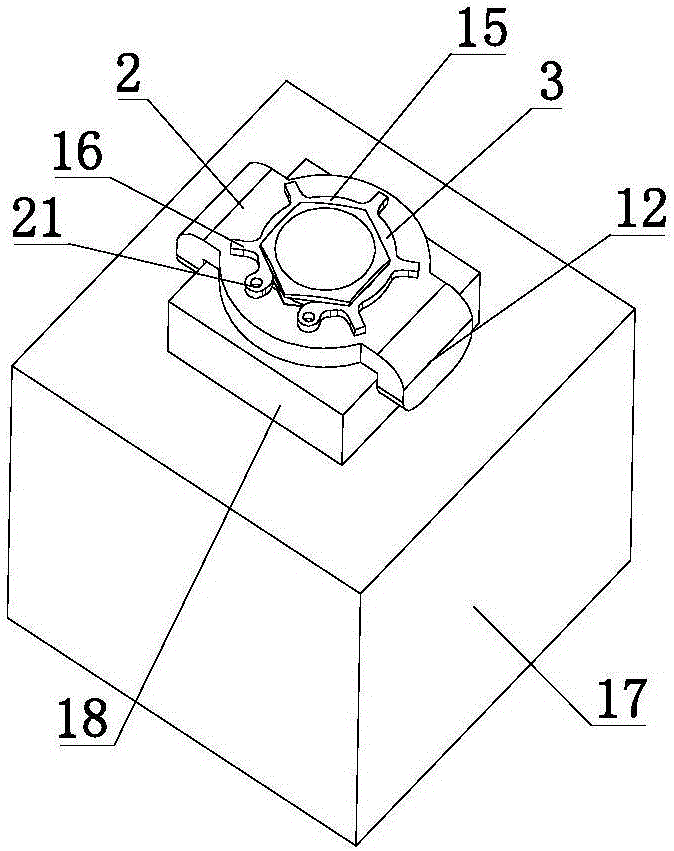
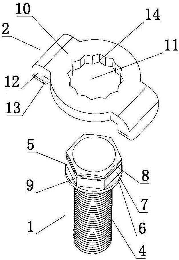
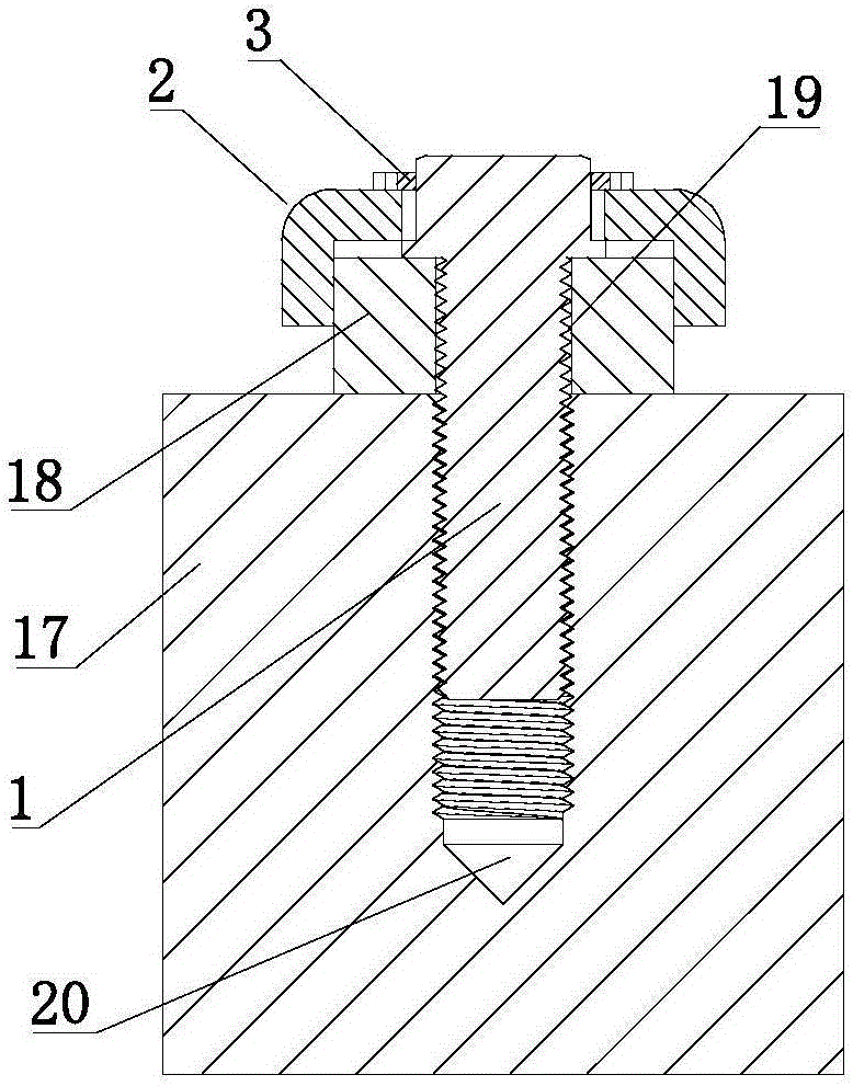
[0178] like Figure 1 to Figure As shown in 3, a fastening connection assembly includes a screw rod 1, an anti-rotation sleeve 2, and a stopper. The stopper is a snap ring 3.

[0179] The screw 1 includes an external threaded portion 4 and a rotation-stop resisting portion 5 arranged in sequence. The anti-rotation resisting portion 5 includes a cylindrical anti-rotation convex ring 6 and a regular hexagonal anti-rotation portion 7 , the anti-rotation convex ring 6 is placed between the external thread portion 4 and the anti-rotation portion 7 . The anti-rotation part 7 is provided with a locking groove 8 that cooperates with the snap ring 3 , and six planes on the outer periphery of the anti-rotation part 7 form six anti-rotation parts 9 of the screw rod arranged in the circumferential direction. The resisting ring 6 protrudes radially from the external threaded portion 4 and the anti-rotation portion 7 .

[0180] The anti-rotation sleeve 2 includes an annular anti-rotation...

Embodiment 2

[0187] like Figure 4 to Figure As shown in FIG. 7 , a fastening connection assembly includes a screw rod 31 , a lock nut 32 , and an anti-rotation sleeve 40 .

[0188] The screw 31 includes an external threaded portion 33 and an external gear-shaped anti-rotation blocking portion 34 arranged in sequence, and the anti-rotation blocking portion 34 radially protrudes from the external threaded portion 33 . A plurality of trapezoidal teeth are evenly arranged in the circumferential direction on the outer periphery of the anti-rotation resisting portion 34 , and one trapezoidal tooth forms a screw anti-rotation portion 35 .

[0189] The outer circumference of the locking nut 32 includes a regular hexagonal clamping portion 36, a conical resisting portion 37 and an axial anti-rotation boss 38 arranged on the end surface of the resisting portion 37. The axial center of the locking nut 32 is provided with a The threaded through hole 39 matched with the external threaded part 33 of 3...

Embodiment 3

[0197] like Figure 8 to Figure As shown in 10 , a fastening connection assembly includes a screw rod 401 , a locking nut 402 , an anti-rotation sleeve 403 , and a stopper, and the stopper is a resisting nut 404 .

[0198] The locking nut 402 is stepped, and includes a regular hexagonal clamping portion 405 and an external gear-shaped anti-rotation portion 406 , the anti-rotation portion 406 radially protrudes from the clamping portion 405 . A clamping portion 405 is provided to facilitate the clamping of the lock nut 402 by a wrench when the lock nut 402 is installed and disassembled. A plurality of triangular teeth evenly arranged in the circumferential direction are arranged on the outer periphery of the anti-rotation part 406 , one triangular tooth forms an outer anti-rotation part 407 of the nut, and a threaded through hole 409 is provided at the axial center.

[0199] The screw 401 includes an external threaded part 410 matched with the threaded through hole 409 of the ...


PUM


Abstract

Disclosed is a fastening connection structure. The fastening connection structure comprises a fastening connection assembly, a parent body and an appendage. The fastening connection assembly comprises a screw and a screw rotation stop sleeve. The hole wall of a rotation stop through hole of the screw rotation stop sleeve is provided with an axial screw rotation stop sleeve inner rotation stop part matched with a resisting part outer rotation stop part of the screw. A screw rotation stop sleeve rotation stop convex part is arranged on the periphery of the screw rotation stop sleeve. The appendage is provided with an appendage rotation stop convex part. The screw connects the parent body with the appendage together in a fastening mode. The resisting part outer rotation stop part and the screw rotation stop sleeve inner rotation stop part restrain the screw from rotating relative to the screw rotation stop sleeve in a resisting matched mode. The appendage rotation stop convex part resists the screw rotation stop sleeve rotation stop convex part circumferentially on one side of the screwed-in direction of the screw so as to restrain the screw rotation stop sleeve from rotating relative to the appendage in a matched mode. The screw, the appendage and the parent body are installed together non-rotationally. The fastening connection structure has the advantages that a rotation stop part is not needed, a rotation stop hole does not need to be machined in the appendage, installation and taking-out of the rotation stop sleeve are fast, convenient and reliable, and the screw does not rotate reversely or get loose.

Description

[0001] Technical field: [0002] The invention relates to a fastening connection technology for statically connecting two or more objects with threaded pairs; in particular, it relates to a method for statically connecting crankshaft linkage mechanisms, track structures, aircraft, ships, equipment, aerospace equipment, etc. through threaded pairs. Aircraft carrier, spaceship, rocket, engine, nuclear reaction equipment, train, high-speed rail, rail, steel structure building, steel structure bridge, automobile, etc. Fastening connection components and fastening connection structures and tracks of mechanical parts on key parts of mechanical equipment structure, the use environment of these mechanical parts is particularly harsh, such as large vibration, high temperature environment, heavy load, etc., and the connection reliability of the threaded mechanical static connection is particularly high. Background technique [0003] The thread pair mechanical static connection between o...

Claims


Application Information

Patent Timeline
Patent Type & Authority Applications(China)
IPC IPC(8): F16B39/28F16B35/06F16B37/00E01B9/12
CPCF16B39/10F16B39/108
Inventor 杨东佐
Owner 杨东佐
Why Eureka
Try Eureka